Category Archives: Marine

Lun MD-160 Ekranoplan cruiser

Lun-class / Spasatel Ekranoplans

By William Pearce

In March 1980, the Soviet government envisioned a fast-attack force utilizing missile-carrying ekranoplans. An ekranoplan (meaning “screen plane”), also known as wing-in-ground effect (WIG) or ground-effect-vehicle (GEV), is a form of aircraft that operates in ground effect for added lift. The machines typically operate over water because of their need for large flat surfaces.

Lun MD-160 Ekranoplan moored

The missile-carrying Lun ekranoplan at rest on the Caspian Sea. The craft exhibits worn paint in the undated photo. Note the gunner’s station just below the first missile launcher. A Mil Mi-14 helicopter is in the background.

When the missile-carrying ekranoplan was being considered, the huge KM (Korabl Maket) ekranoplan was being tested, and testing was just starting on the three production A-90 Orlyonok transport ekranoplans. Known as Project 903, the missile-carrying Lun-class ekranoplans would be built upon the lessons learned from the earlier machines. The word “lun” (лунь) is Russian for “harrier.” An order for four examples was initially considered, with the number soon jumping to 10 Lun-class machines.

The first Lun-class ekranoplan was designated S-31, with some sources stating the designation MD-160 was also applied. Most sources referred the craft simply as “Lun.” The Lun was designed by Vladimir Kirillovykh at the Alekseyev Central Hydrofoil Design Bureau in Gorky (now Nizhny Novgorod), Russia. The new craft differed from previous ekranoplans by not having dedicated cruise engines.

Lun MD-160 Ekranoplan at speed

The Lun at speed traveling over the water’s surface. Note the contoured, heat-resistant surface behind each missile tube to deflect the exhaust of the launching missile. The large domes on the tail are evident in this image.

The Lun’s all-metal fuselage closely resembled that of a flying boat with a stepped hull. Mounted just behind the cockpit were eight Kuznetsov NK-87 turbojets, each capable of 28,660 lbf (127.5 kN) of thrust. The engines were mounted in sets of four on each side of the Lun. The nozzle of each jet engine rotated down during takeoff to increase the air pressure under the Lun’s wings (power augmented ram thrust). This helped the craft rise from the water’s surface and into ground effect. The nozzles were positioned straight back for cruise flight.

Lun MD-160 Ekranoplan ship

With flaps down, the Lun passes by a Soviet Navy ship. The rear gunner’s position is just visible at the rear of the craft.

The mid-mounted, short span wings had a wide cord and an aspect ratio of 3.0. Six large flaps made up the trailing edge of each wing, with the outer flaps most likely operating as flaperons (a combination flap and aileron). The tip of each wing was capped by a flat plate that extended down to form a float. A single hydro-ski was positioned under the fuselage, where the wings joined. The hydraulically-actuated ski helped lift the craft out of the water as it picked up speed. A swept T-tail with a split rudder at its trailing edge rose from the rear of the fuselage. Radomes in the tail’s leading edge housed equipment for navigational and combat electronics. The large, swept horizontal stabilizer had large elevators mounted to its trailing edges.

Lun MD-160 Ekranoplan cruiser

Looking more like an alien ship out of a science fiction movie than a cold-war experiment, the Lun was an impressive sight. Note the chines on the bow to help deflect water from the engines.

Mounted atop the Lun were three pairs of angled missile launchers. No cruise engines were mounted to the Lun’s tail over concerns that the engines would cut out when they ingested the exhaust plume from a missile launch. The launchers carried the P-270 (3M80) Moskit—a supersonic, ramjet-powered, anti-ship cruise missile. The P-270 traveled at 1,200 mph (1,930 km/h) and had a range of up to 75 miles (120 km). The belief was that the Lun-class ekranoplans would be able to close in on an enemy ship undetected and launch the P-270 missile, which would be nearly unstoppable to the enemy ships. The Lun also had two turrets, each with two 23 mm cannons. One turret was forward-facing and positioned below the first pair of missile launchers. The second turret was rear-facing and positioned behind the Lun’s tail.

Lun MD-160 Ekranoplan Kaspiysk

View of the Lun in March 2009 as it sits slowly deteriorating at the Kaspiysk base on the Caspian Sea. The special dock was made for the Lun. The dock was towed out to sea and submerged to allow the Lun to either float free for launch or be recovered.

The Lun had a wingspan of 144 ft 4 in (44.0 m), a length of 242 ft 2 in (73.8 m), and a height of 62 ft 11 in (19.2 m). The craft had a cruise speed of 280 mph (450 km/h) and a maximum speed of 342 mph (550 km/h). Operating height was from 3 to 16 ft (1 to 5 m), and the Lun had an empty weight of 535,723 lb (243,000 kg) and a maximum weight of 837,756 lb (380,000 kg). The craft had a range of 1,243 miles (2,000 km) and could operate in seas with 9.8 ft (3 m) waves. The Lun had a crew of 15 and could stay at sea for up to five days.

The Lun was launched on the Volga River on 16 July 1986. Operating from the base at Kaspiysk, Russia, testing occurred on the Caspian Sea from 30 October 1989 to 26 December. By that time, plans for the Lun-class of missile-carrying ekranoplans had faded, and the decision was made that only one of the type would be built. The Lun was withdrawn from service sometime in the 1990s and stored at Kaspiysk, where it remains today. In 2002, there was talk of reviving the missile-carrying ekranoplan, but no action was taken.

Lun MD-160 Ekranoplan Kaspiysk igor113

An interesting view of the Lun sitting at Kaspiysk in late-2009. Note the downward angle of the jet nozzles, and the flaps appear to be disconnected. The elements have taken a toll on the ekranoplan. (igor113 image)

The second machine (S-33), which was about 75-percent complete, was converted to serve as a Search and Rescue (SAR) craft. This decision was in part due to the loss of the K-278 Komsomolets submarine on 7 April 1989. A fire caused the loss of the submarine, and 42 of the 69-man crew died, many from hypothermia as they awaited rescue. This accident illustrated the need for a fast-response SAR craft.

Spasatel Ekranoplan Volga

The Spasatel in mid-2014 at the Volga Shipyard with a protective wrap to help preserve the craft. The wings and horizontal stabilizers are resting on the ekranoplan’s back. Note the machine’s reinforced spine. (rapidfixer image)

For its new purpose, S-33 was named Spasatel for “Rescuer.” Conversion work was started around 1992. The Spasatel had the same basic configuration as the Lun but had a reinforced spine and an observation deck placed atop its tail. The Spasatel possessed the same dimensions and performance as the Lun. However, sources state that the Spasatel would fly out of ground effect. For sea search missions, the craft would fly at an altitude of 1,640 ft (500 m), and it had a ceiling of 24,606 ft (7,500 m). The Spasatel had a range of 1,864 miles (3,000 km).

Spasatel Ekranoplan Volga Andrey Orekhov

The Spasatel seen in late 2018 at the Volga / Krasnoye Sormovo Shipyard in Nizhny Novgorod. The craft has been outside and exposed to the elements since 2016. Note the observation deck incorporated into the tail. (Андрей Орехов / Andrey Orekhov image)

The SAR ekranoplan would be quickly altered based on its mission. The Spasatel could carry up to 500 passengers, or temporarily hold 800 people for up to five days waiting for rescue. As a hospital ship, 80 patients could be treated on the Spasatel. A tank with 44,092 lb (20,000 kg) of fire retardant could be mounted atop the Spasatel for fighting fires on ships or oil platforms. Or, a submersible with space for 24 people could be mounted on the Spasatel for responding to submarine accidents. The Spasatel could even respond to oil spills and lay out 9,843 ft (3,000 m) of barriers. Even more ambitious was the noble plan to have several Spasatel ekranoplans in-service around the world ready to respond to any call of marine distress at a moment’s notice.

The Spasatel was about 80-percent complete when work was halted in the mid-1990s due to a lack of funds. In 2001, there was renewed hope that the Spasatel would be completed, but again, no money was forthcoming. The Spasatel was housed in the construction building at the Volga Shipyard until 2016, when it was moved outside. In 2017, there was again some hope that the Spasatel would be completed, now for SAR missions in the Arctic. Under this plan, work on the Spasatel would continue from 2018 until its completion around 2025. However, it does not appear that any work has been done, and the Spasatel continues to deteriorated as it sits exposed to the elements.

Spasatel Ekranoplan Model

Spasatel model from 2017 depicting its new purpose as an artic rescue craft. It does not appear that any work has been performed on the actual machine, but who knows what the future may hold. (Valery Matytsin/TASS image via The Drive)

Sources:
Soviet and Russian Ekranoplans by Sergy Komissarov and Yefim Gordon (2010)
WIG Craft and Ekranoplan by Liang Lu, Alan Bliault, and Johnny Doo (2010)
https://s1rus.livejournal.com/154716.html
https://www.thedrive.com/the-war-zone/15542/russia-supposedly-bringing-back-giant-ekranoplans-for-arctic-missions
http://iiaat.guap.ru/?n=main&p=pres_spasatel
https://en.wikipedia.org/wiki/Spasatel
https://igor113.livejournal.com/51213.html
https://igor113.livejournal.com/52174.html
https://igor113.livejournal.com/52878.html

Alexeyev A-90 Orlyonok top

Alexeyev SM-6 and A-90 Orlyonok Ekranoplans

By William Pearce

Rostislav Alexeyev (sometimes spelled Alekeyev) of the Central Hydrofoil Design Bureau (CHDB or Tsentral’noye konstruktorskoye byuro na podvodnykh kryl’yakh / TsKB po SPK) had been working out of the Krasnoye Sormovo Shipyard in Gorky (now Nizhny Novgorod), Russia since the 1940s. In the 1950s, Alexeyev began experimental work with ekranoplans (meaning “screen planes”), also known as wing-in-ground effect (WIG) or ground-effect-vehicle (GEV). His work led to the construction of the massive, experimental KM (Korabl Maket or ship prototype) ekranoplan in the mid-1960s.

Alexeyev SM-6 rear

The SM-6 was a 50-percent scale proof-of-concept vehicle for the A-90 Orlyonok ekranoplan. First flown in 1971, testing of the SM-6 continued until the mid-1980s.

As work on the KM was underway, the Soviet Navy expressed interest in a troop transport ekranoplan, and Alexeyev had started design studies of such a craft as early as 1964. In 1966, the decision was made to construct a 50-percent scale test model of the troop transport. The test ekranoplan was designated SM-6 (samokhodnaya model’-6 or self-propelled model-6).

The SM-6 had a flying boat-style stepped hull that was made of steel and aluminum. The two-place, side-by-side cockpit was near the front of the machine and covered with a large canopy. Two hydro-skis were placed under the hull: one under the nose (bow) and one under the wings. The hydraulically-actuated skis helped lift the craft out of the water as it picked up speed.

Alexeyev SM-6 square

An undated image of the SM-6 on display at Lenin Square in Kaspiysk, Russia. The ekranoplan has since been removed, and its fate is unknown. However, another undated image shows the its derelict fuselage (hull) in a sorry state.

Mounted in the SM-6’s nose were two Milkulin RD-9B jet engines, each of which produced 4,630 lbf (20.6 kN) of thrust. The inlets for the engines were in the upper surface of the nose, and the nozzles protruded out the sides of the SM-6, just behind and below the cockpit. For takeoff, the jet nozzle of each engine was rotated down to increase air pressure under the craft’s wings (power augmented ram thrust). In cruise flight, the nozzles were pointed back for forward thrust.

The low-mounted wing had a short span and a wide cord, and had an aspect ratio of 2.8. Five flaps were attached along each wing’s trailing edge. The outer flaps most likely acted as flaperons, a combination flap and aileron, but definitive proof has not been found. The tip of each wing extended down to form a float. A large vertical stabilizer extended from the rear of the craft. A rudder was positioned on the trailing edge of the vertical stabilizer. When the SM-6 was on the water’s surface, the bottom part of the rudder was submerged and helped steer the craft. Mounted atop the tail was a 3,750 shp (2,796 kW) Ivchenko AI-20K turboprop engine driving a four-blade propeller that was approximately 12 ft (3.65 m) in diameter. Behind the engine and atop the tail was the large horizontal stabilizer with swept leading and trailing edges. Large elevators were incorporated into the trailing edges of the horizontal stabilizer.

Alexeyev A-90 Orlyonok top

The A-90 Orlyonok cruising above the Caspian Sea. The jet intakes positioned atop the bow helped reduce the amount of water ingested into the engines and kept the craft rather streamlined.

The SM-6 had a wingspan of 48 ft 7 in (14.8 m), a length of 101 ft 8 in (31.0 m), and a height of 25 ft 9 in (7.85 m). The craft had a cruise speed of 186 mph (300 km/h) and a maximum speed of 217 mph (350 km/h). Its operating height was from 2 to 5 ft (.5 to 1.5 m), and the SM-6 had a maximum weight of 58,422 lb (26,500 kg). The craft had a range of 435 miles (700 km) and could operate in seas with 3.3 ft (1.0 m) waves.

Construction of the SM-6 started in October 1966 at the Krasnoye Sormovo Shipyard. Insufficient funding caused some delays, and the SM-6 was not finished until 30 December 1970. At that time, the Volga Shipyard was established as an experimental production facility of the CHDB and operated out of the same plant in which the SM-6 was built. The CHDB was also renamed the Alekseyev Central Hydrofoil Design Bureau.

Alexeyev A-90 Orlyonok cargo

The entire front of the Orlyonok swung open to allow access to the cargo hold. A 22,708 lb (10,300 kg) BTR-60PB armored personnel carrier is seen loaded on the Orlyonok. Note the engine’s exhaust nozzle and the machine gun turret.

In July 1971, the SM-6 was transported about 53 miles (85 km) up the Volga River to Chkalovsk, Russia. Initial tests of the craft were conducted in August 1971 on the Gorky Reservoir. In early 1972, the SM-6 was successfully tested on ice and snow. In 1973, modifications were made that included mounting wheels to the hydro-skis. The wheels were used as beaching gear, allowing the SM-6 to power itself out of the water and onto land, or vice versa. Having proven itself as a fully functioning ekranoplan, the SM-6 was transferred to the Kaspiysk base on the Caspian Sea in late 1974. The SM-6 continued to undergo modifications and testing until the mid-1980s. At different points in its career, the SM-6 was marked as 6M79 and 6M80. After it was withdrawn from service, the SM-6 was displayed for a number of years at a public square (Lenin Square?) in Kaspiysk. The elements took a toll on the ekranoplan, and it was eventually removed from the square. The derelict remains of the SM-6 sat near the shore of the Caspian Sea for a time, and mostly likely, the machine was later scrapped.

Following the successful tests of the SM-6 in 1971, plans moved forward for constructing a full-scale, troop transport ekranoplan. The full-size ekranoplan was known as the A-90 Orlyonok (Eaglet) or Project 904. Although twice its size, the Orlyonok had mostly the same configuration as the SM-6.

Alexeyev A-90 Orlyonok front

The Orlyonok’s beaching gear allowed the craft to propel itself out of the water and onto a hard surface. The turning arc of the nose wheel has not been found, but with the main wheels under the wing, the Orlyonok may have been able to turn rather sharply on land.

Mounted in the Orlyonok’s nose (bow) were two Kuznetsov NK-8-4K jet engines that provided 23,149 lbf (103.0 kN) of thrust each. Just behind the craft’s cockpit was a turret with two 12.7-mm (.50-Cal) machine guns. The entire nose of the Orlyonok, including its cockpit, swung open to the right a maximum of 92 degrees. A set of folding ramps allowed for direct entry into the machine’s cargo hold, which was 68 ft 11 in (21.0 m) long, 9 ft 10 in (3.0 m) wide, and 10 ft 6 in (3.2 m) tall. The hold could carry 250 troops or 44,092 lb (20,000 kg) of equipment, including armored vehicles.

The beaching gear mounted to the hydro-skis consisted of a steerable, two-wheel nose unit and a ten-wheel main unit under the hull. The low-mounted wing had a short span and a wide cord, with an aspect ratio of 3.0. The trailing edge of the wing had flaperons at its tips with flaps spanning the rest of the distance. The tip of each wing extended down to form a float. A large vertical stabilizer extended from the rear of the craft. Mounted atop the tail was a 15,000 ehp (11,186 kW) Kuznetsov NK-12MK turboprop engine driving an eight-blade, contra-rotating propeller that was approximately 19 ft 8 in (6.0 m) in diameter. The Orlyonok was equipped with a full-range of navigational and combat electronics.

Alexeyev A-90 Orlyonok slow

At low speed, a fair amount of spray enveloped the Orlyonok. The circular markings on the sides of the craft designated over-wing access doors, which were actually rectangular.

The Orlyonok had a wingspan of 103 ft 4 in (31.5 m), a length of 190 ft 7 in (58.1 m), and a height of 52 ft 2 in (15.9 m). The craft had a cruise speed of 224 mph (360 km/h) and a maximum speed of 249 mph (400 km/h). Operating height was from 2 to 16 ft (.5 to 5.0 m). The Orlyonok had an empty weight of 220,462 lb (100,000 kg) and a maximum weight of 308,647 lb (140,000 kg). The craft had a range of 932 miles (1,500 km) and could operate in seas with 6.6 ft (2.0 m) waves.

The Orlyonok prototype was built at the Volga Shipyard and made its first flight in 1972, taking off from the Volga River. The craft was later disguised as a Tupolev Tu-134 airliner fuselage and transported by barge to the Kaspiysk base on the Caspian Sea for further testing. In 1975, the prototype was accidently beached on a rocky sandbar. The craft was able to power itself back into the water, but the hull was damaged and its structural integrity was compromised. The damage went undetected until the rear fuselage and tail broke off during a landing on rough seas. Alexeyev was onboard and took control of the crippled ekranoplan. Using full-power of the bow jet engines, Alexeyev as able to keep the open back of the hull above water and return to base. The authorities attributed the accident to a design deficiency and blamed Alexeyev, who was removed as the chief designer and reassigned to experimental work.

Alexeyev A-90 Orlyonok GKS-13

The Orlyonok prototype flies past a Soviet Navy ship on the Caspian Sea. Unlike the SM-6, the Orlyonok’s rudder did not extend into the water when the craft was on the sea.

The Russian Navy had been sufficiently impressed by the Orlyonok to order three production machines and a static test article. The damaged prototype was returned to the Volga Shipyard and completely rebuilt as the first production Orlyonok, S-21 (610), which was completed in 1978 and delivered to the Navy on 3 November 1979. The second Orlyonok, S-25 (630), was completed in 1979 and delivered on 27 October 1981. The final Orlyonok, S-26 (650), was completed in 1980 and delivered on 30 December 1981. Plans to produce an additional eight units were ultimately abandoned.

The three Orlyonoks were tested and operated for several years on the Caspian Sea. The captain and crew of S-21 took it upon themselves to test the machine to its limits. Away from witnesses and in the middle of the Caspian Sea, S-21 was flown out of ground effect and up to 328 ft (100 m) for an extended time. At that height, the ekranoplan was sluggish, unstable, and a challenge to fly, but positive control was maintained.

Alexeyev A-90 Orlyonoks

Two production Orlyonoks at Kaspiysk on the Caspian Sea. Note the open over-wing doors and the open engine access panel of the first machine.

By 1989, the three Orlyonoks had performed a total of 438 flights and 118 beachings. On 12 September 1992, S-21 was lost when a control malfunction coupled with pilot error caused it to rise to 130 ft (40 m) and stall. One member of the ten-man crew was killed, and S-21 was eventually sunk by the Navy—the cost of salvaging the craft was too high. Reportedly, the last Orlyonok flight was made by S-26 in late 1993, after which, the Orlyonoks fell into a state of disuse followed by disrepair.

In 1998, the Navy wrote off the two remaining Orlyonoks. Around 2000, S-25 was scrapped, but S-26 was somehow preserved. In 2006, S-26 was given to the Museum and Memorial Complex of the History of the Navy of Russia (Muzeyno-Memorial’nyy Kompleks Istorii Vmf Rossii) located on the Volga River in Moscow. The S-26 was demilitarized in 2007 and restored and installed at the museum in 2008. The Orlyonok design inspired other military and commercial ekranoplan design, but none were built.

Alexeyev A-90 Orlyonok 2008

Orlyonok S-26 shortly after it was put on display at the Naval museum in Moscow. The wheels of the beaching gear are visible, although it appears the main set is missing two wheels. Sadly, the condition of the impressive ekranoplan has deteriorated over the years. (Alex Beltyukov image via Wikimedia Commons)

Sources:
Soviet and Russian Ekranoplans by Sergy Komissarov and Yefim Gordon (2010)
WIG Craft and Ekranoplan by Liang Lu, Alan Bliault, and Johnny Doo (2010)
https://aviationhumor.net/the-last-flight-of-the-soviet-beach-assault-ekranoplan-a-90-orlyonok/#
http://www.volga-shipyard.com/index.php?section=history&lang=eng

Alexeyev KM rear

Alexeyev KM Ekranoplan (Caspian Sea Monster)

By William Pearce

Rostislav Alexeyev (sometimes spelled Alekeyev) was born in Novozybkov, Russia on 18 December 1916. On 1 October 1941, he graduated from the Gorky Industrial Institute (now Gorky Polytechnic Institute) as a shipbuilding engineer. Alexeyev was sent to work at the Krasnoye Sormovo Shipyard in Gorky (now Nizhny Novgorod), Russia. In 1942, Alexeyev was tasked to develop hydrofoils for the Soviet Navy, work that was still in progress at the end of World War II. However, there was sufficient governmental interest for Alexeyev to continue his hydrofoil studies after the war. This work led to the development of the Raketa, Meteor, Kometa, Sputnik, Burevestnik, and Voskhod passenger-carrying hydrofoils spanning from the late 1940s to the late 1970s.

Alexeyev SM-2

The SM-2 was the first ekranoplan that possessed the same basic configuration later used on the KM. The nozzle of the bow (booster) engine is visible on the side of the SM-2. The intake for the rear (cruise) engine is below the vertical stabilizer. Note the three open cockpits.

Alexeyev appreciated the speed of the hydrofoil but realized that much greater speeds could be achieved if the vessel traveled just above the water’s surface. Wings with a short span and a wide cord could be attached to a vessel to lift its hull completely out of the water as it traveled at high speed, allowing it to ride on a cushion of air. Such a craft would take advantage of the ground (screen) effect as air is compressed between the craft and the ground. In Russian, this type of vessel is called an ekranoplan, meaning “screen plane.” They are also known as wing-in-ground effect (WIG) or a ground-effect-vehicle (GEV), since the craft’s wing must stay near the surface and in ground effect. Because ground effect vehicles fly without contacting the surface, they are technically classified as aircraft. However, ground effect vehicles need a flat surface over which to operate and are typically limited to large bodies of water, even though they can traverse very flat expanses of land. Because they operate from water, ground effect vehicles are normally governed by maritime rules.

In the late 1950s, Alexeyev and his team began work on several scale, piloted, test machines to better understand the ekranoplan concept. The first was designated SM-1 (samokhodnaya model’-1 or self-propelled model-1) and made its first flight on 22 July 1961. The SM-1 was powered by a single jet engine and had two sets (mid and rear) of lifting wings. Lessons learned from the SM-1 were incorporated into the SM-2, which was completed in March 1962. The SM-2 had a single main wing and a large horizontal stabilizer. The craft also incorporated a booster jet engine in its nose (bow) to blow air under the main wing to increase lift (power augmented ram thrust). The SM-2 was demonstrated to Premier of the Soviet Union Nikita Khrushchev, who then lent support for further ekranoplan development to Alexeyev and his team.

Alexeyev SM-5

The SM-5 was a 25-percent scale version of the KM. The craft followed the same basic configuration as the SM-2 but was more refined. The structure ahead of the dorsal intake was to deflect sea spray.

Ekranoplan design experimentation was expanded further with the SM-3. The craft had very wide-cord wings and was completed late in 1962. That same year, Alexeyev began working at the Central Hydrofoil Design Bureau (CHDB or Tsentral’noye konstruktorskoye byuro na podvodnykh kryl’yakh / TsKB po SPK). In 1963, the next test machine, the SM-4, demonstrated that a good understanding of ekranoplan design had been achieved. Also in 1963, the Soviet Navy placed an order for a large, experimental ekranoplan transport known as the KM (Korabl Maket or ship prototype).

While the CHDB began design work on the KM, the SM-5 was built in late 1963. The SM-5 was a 25-percent scale model of the KM and was powered by two Mikulin KR7-300 jet engines. The craft had a wingspan of 31 ft 2 in (9.5 m), a length of 59 ft 1 in (18.0 m), and a height of 18 ft 1 in (5.5 m). The SM-5 had a takeoff speed of 87 mph (140 km/h), a cruise speed of 124 mph (200 km/h), and a maximum speed of 143 mph (230 km/h). Its operating height was from 3 to 10 ft (1 to 3 m), and the craft had a maximum weight of 16,094 lb (7,300 kg). The SM-5 could operate in seas with 3.9 ft (1.2 m) waves. Initial tests of the SM-5 were so successful that the decision was made to construct the KM without building a larger scale test machine. Sadly, the SM-5 was destroyed, and its two pilots were killed in a crash on 24 August 1964. During a test, a strong wind was encountered that caused the craft to gain altitude. Rather than reduce power, the pilot added power. The SM-5 rose out of ground effect and stalled.

Alexeyev KM at speed

The KM (Korabl Maket) at speed on the Caspian Sea. Note the “04” tail number and the spray deflectors covering the cruise engine intakes on the vertical stabilizer.

The KM’s all-metal fuselage closely resembled that of a flying boat with a stepped hull. Mounted just behind the cockpit were eight Dobrynin VD-7 turbojets, with four engines mounted in parallel on each side of the KM. Each VD-7 was capable of 28,660 lbf (127.5 kN) of thrust. The jet nozzle of each engine rotated down during takeoff to increase the air pressure under the craft’s wings. These engines were known as boost engines.

The shoulder-mounted, short span wings had a wide cord and an aspect ratio of 2.0. Two large flaps made up the trailing edge of each wing. The tip of each wing was capped by a flat plate that extended down to form a float. Two additional VD-7 turbojets were mounted near the top of the KM’s large vertical stabilizer. These engines were known as cruise engines and were used purely for forward thrust. A heat-resistant panel covered the section of the rudder just behind the cruise engines. At low speeds, the rudder extended into the water and helped steer the KM. Atop the vertical stabilizer was the horizontal stabilizer, which had about 20 degrees of dihedral. A large elevator was mounted to the trailing edge of the horizontal stabilizer.

Alexeyev KM top

The servicemen atop the KM help illustrate the craft’s immense size. Note the access hatches in the wings. This view also shows the ekranoplan’s large control surfaces. The nozzles of the left engines are in the down (boost/takeoff) position while the nozzles on the right are in the straight (cruise flight) position.

The KM had a wingspan of 123 ft 4 in (37.6 m), a length of 319 ft 7 in (97.4 m), and a height of 72 ft 2 in (22.0 m). The craft had a cruise speed of 267 mph (430 km/h) and a maximum speed of 311 mph (500 km/h). Operating height was from 13 to 46 ft (4 to 14 m), and the KM had an empty weight of 529,109 lb (240,000 kg) and a maximum weight of 1,199,313 lb (544,000 kg). The craft had a range of 932 miles (1,500 km) and could operate in seas with 11.5 ft (3.5 m) waves. The KM had a crew of three and could carry 900 troops, but the craft was intended purely for experimental purposes.

The KM was built at the Krasnoye Sormovo Shipyard in Gorky. Alexeyev was the craft’s chief designer and V. Efimov was the lead engineer. The KM was launched on the Volga River on 22 June 1966 and was subsequently floated down the river to the Naval base at Kaspiysk, Russia on the Caspian Sea. To keep the KM hidden during the move, its wings were detached, it was covered, and it was moved only at night. After arriving at the Kaspiysk base, the KM was reassembled, and sea-going trials started on 18 October 1966. V. Loginov was listed as the pilot, but Alexeyev was actually at the controls. At 124 mph (200 km/h), the KM rose to plane on the water’s surface but did not take to the air. Planning tests were continued until 25 October 1966. The early tests revealed that the KM’s hull was not sufficiently rigid and that engine damage was occurring due to water ingestion. Stiffeners were added to the hull, and plans were made to modify the engines.

Alexeyev KM front

While at rest, the KM’s water-tight wings added to the craft’s stability on the water’s surface. Note the far-left engine’s open access panels. Covers are installed in all of the engine intakes.

The first true flight of the KM occurred on 14 August 1967 with Alexeyev at the controls. The flight lasted 50 minutes, and a speed of 280 mph (450 km/h) was reached. Further testing revealed good handling characteristics, and sharp turns were made with the inside wing float touching the water. At one point, the KM was mistakenly flown over a low-lying island for about 1.2 miles (2 km), proving the machine could operate over land, provided it was very flat.

The KM was discovered in satellite imagery by United States intelligence agencies in August 1967. Rather baffled by the craft’s type and intended purpose, the Central Intelligence Agency (CIA) began to refer to the enormous machine as the “Kaspian Monster,” in reference to the KM designation. The “Kaspian Monster” name slowly changed to “Caspian Sea Monster,” which is how the craft is generally known today. The sole KM was painted with at least five different numbers (01, 02, 04, 07, and 08) during its existence. Some sources state the numbers corresponded to different developmental phases, while others contend that the numbers were an attempt to obscure the actual number of machines built.

Alexeyev KM rear

The KM, now with an “07” tail number, cruises above the water. Note the heat resistant panel on the rudder, just behind the exhaust of the cruise jet engines.

While the KM was being built, a second 25-percent scale model was constructed. The model was designated SM-8, and its layout incorporated changes made to the KM’s design that occurred after the SM-5 was built. Like the SM-5, the SM-8 was powered by two Mikulin KR7-300 jet engines. The craft had a wingspan of 31 ft 2 in (9.5 m), a length of 60 ft 8 in (18.5 m), and a height of 18 ft 1 in (5.5 m). The SM-8 had a cruise speed of 137 mph (220 km/h). Operating height was from 3 to 10 ft (1 to 3 m), and the craft had a maximum weight of 16,094 lb (8,100 kg). The SM-8 could operate in seas with 3.9 ft (1.2 m) waves. The craft was first flown in 1968 and tested over a grassy bank in June 1969. The SM-8 also served to train pilots for the KM.

Alexeyev SM-8

The SM-8 was a second 25-percent scale model of the KM and constructed after the loss of SM-5. Its configuration more closely matched that of the KM. The stack above the wings surrounded the intake for the front (booster) engine and deflected sea spray. The front engine was installed so that its exhaust traveled forward to the eight outlets (four on each side) behind the cockpit.

By the late 1960s, the KM had proven that the ekranoplan was a viable means to quickly transport personnel or equipment over large expanses of water. Alexeyev’s focus had moved to another ekranoplan project, the A-90 Orlyonok. By 1979, the KM had been modified by relocating the cruise engines from the vertical stabilizer to a pylon mounted above the cockpit. All engines were fitted with covers to deflect water and prevent the inadvertent ingestion of the occasional unfortunate seabird.

In December 1980, the KM was lost after an accident occurred during takeoff. Excessive elevator was applied and resulted in a relatively high angle of attack. Rather than applying power and correcting the pitch angle, the angle was held and power was reduced. A stall occurred with the KM rolling to the left and impacting the water. The crew escaped unharmed, but the KM was left to slowly sink to the bottom of the Caspian Sea. Reportedly, the craft floated for a week before finally sinking. Either the Soviets were done with the KM, or its immense size prevented reasonable efforts to salvage the machine. From the time it first flew, the KM was the heaviest aircraft in the world until the Antonov An-225 Mriya made its first flight on 21 December 1988. The KM is still the longest aircraft to fly. Experience gained from the KM was applied to the Lun-class S-31 / MD-160.

Alexeyev KM 1979

The KM as seen in 1979 with the cruise engines relocated from the vertical stabilizer to a pylon above the cockpit. A radome is mounted above the engines. All of the engines have been fitted with spray deflectors.

Sources:
Soviet and Russian Ekranoplans by Sergy Komissarov and Yefim Gordon (2010)
WIG Craft and Ekranoplan by Liang Lu, Alan Bliault, and Johnny Doo (2010)
https://en.wikipedia.org/wiki/Rostislav_Alexeyev
https://en.wikipedia.org/wiki/Caspian_Sea_Monster
https://rtd.rt.com/stories/caspian-monster-ekranoplan-vessel/
https://www.theregister.co.uk/2006/09/22/caspian_sea_monster/

Napier-Deltic-T18-37K-Marine-Engine

Napier Deltic Opposed-Piston Diesel Engine

By William Pearce

In 1933, the British engineering firm D. Napier & Son (Napier) acquired licenses to produce the Junkers Jumo 204 and 205 aircraft engines. Napier sought to diversify and expand its aircraft engine business, and the company felt the two-stroke, opposed-piston, diesel engines would usher in an era of safe and fuel-efficient air travel. Napier made some modifications to the Jumo engines, but the internal components were mostly unchanged. The Jumo 204 was built as the Napier Culverin (E102), and the Jumo 205 was planned as the Napier Cutlass (E103). The Culverin was first run on 24 September 1934, but the engine garnered little interest and no orders. By 1936, after only seven Culverins were made and no Cutlasses, Napier halted further work on opposed-piston diesel aircraft engines. English Electric took over Napier in November 1942.

Napier-Deltic-E130-Three-cylinder-test-engine

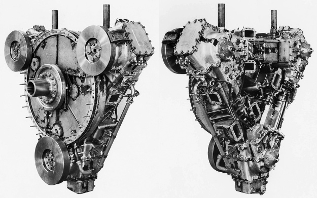
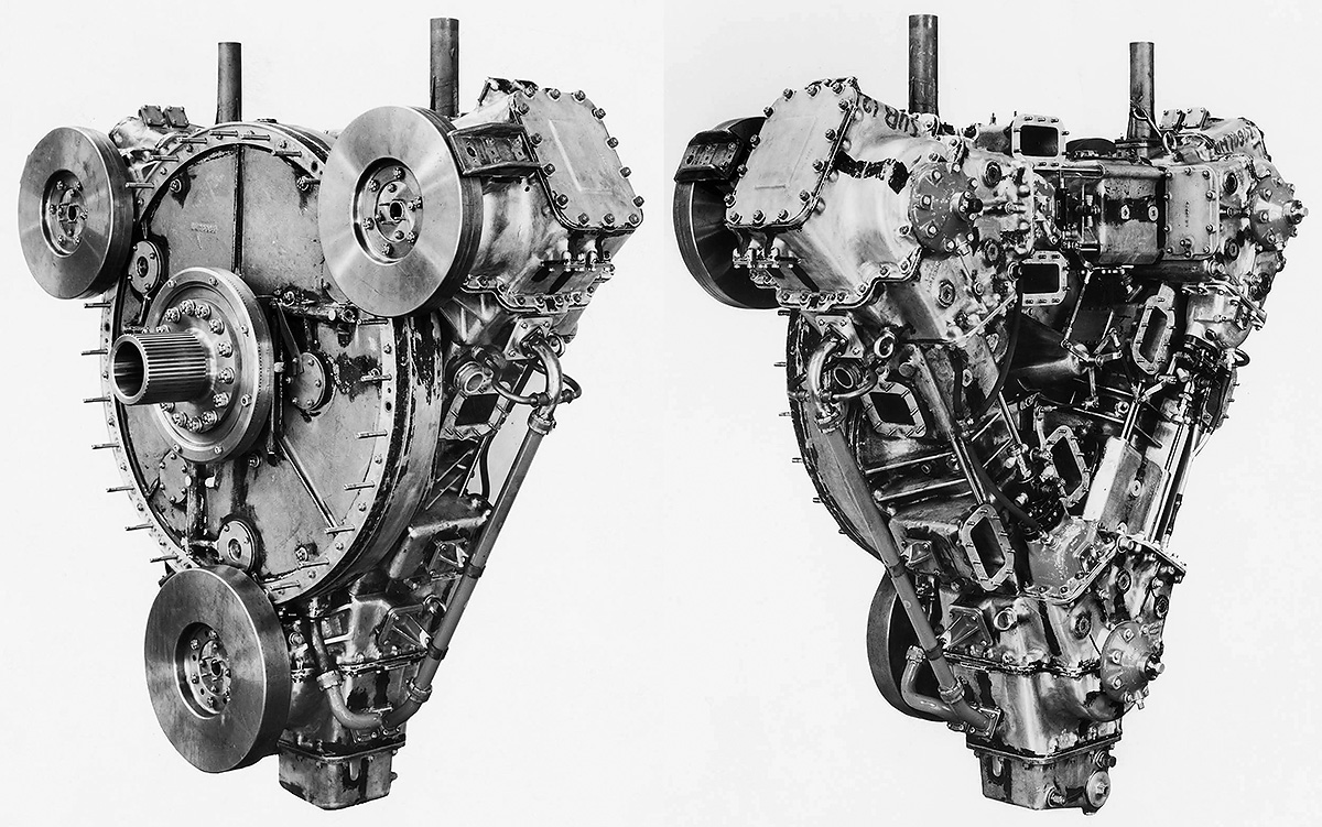
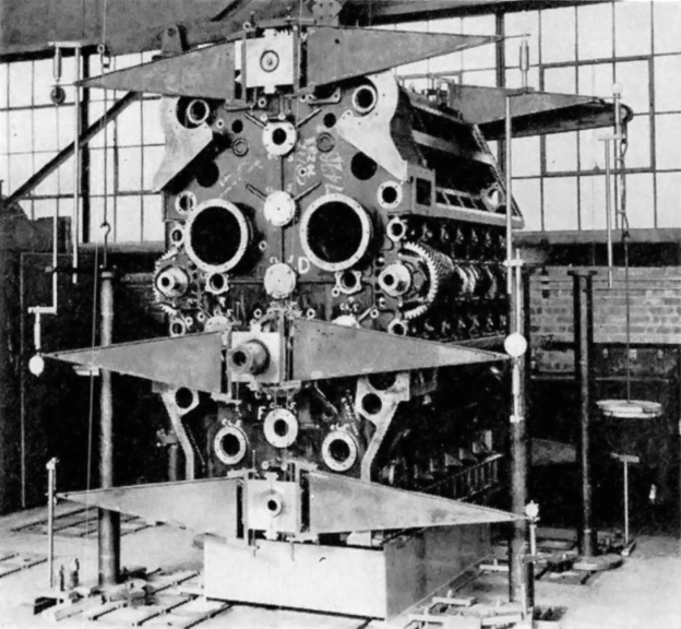
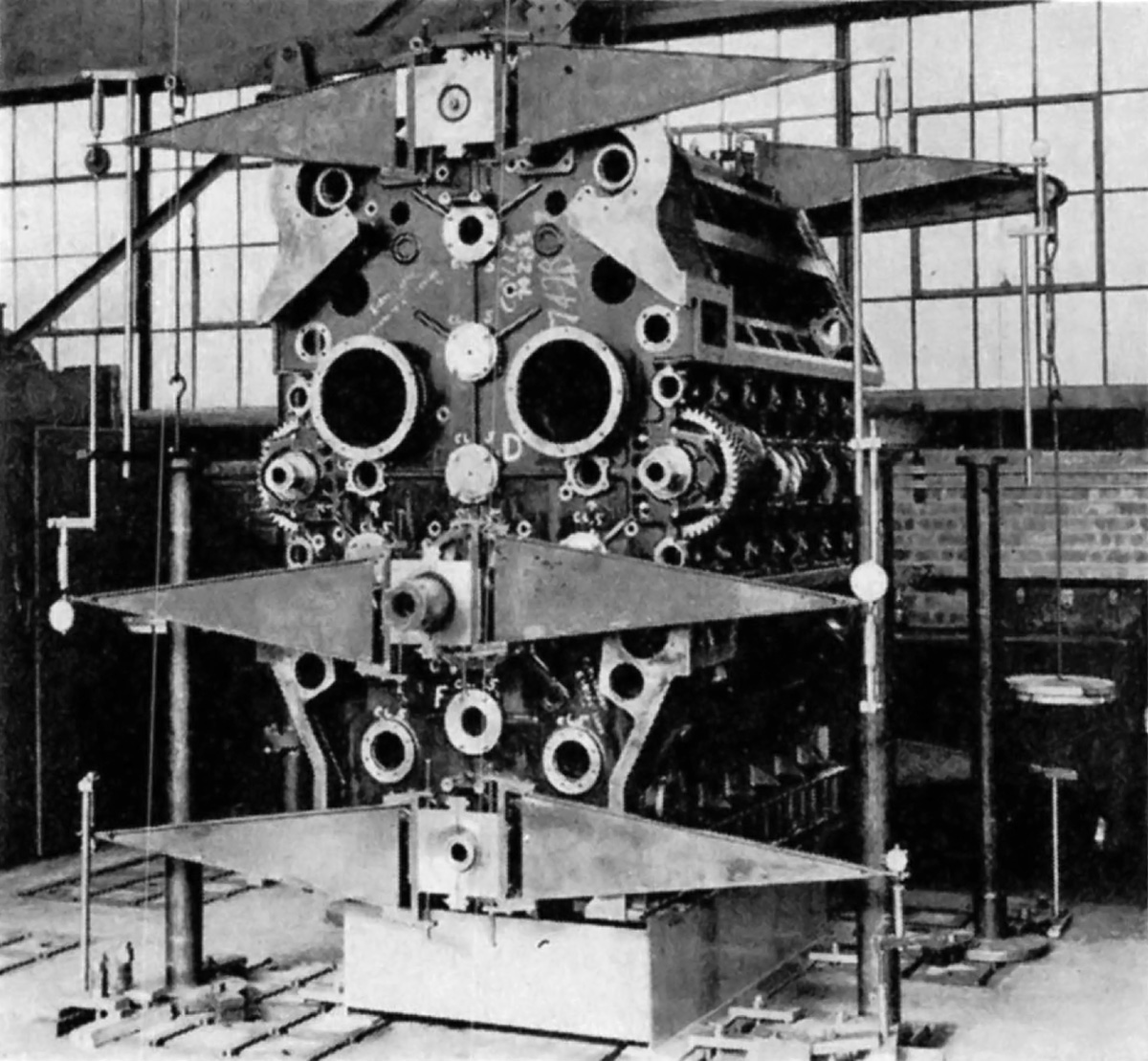
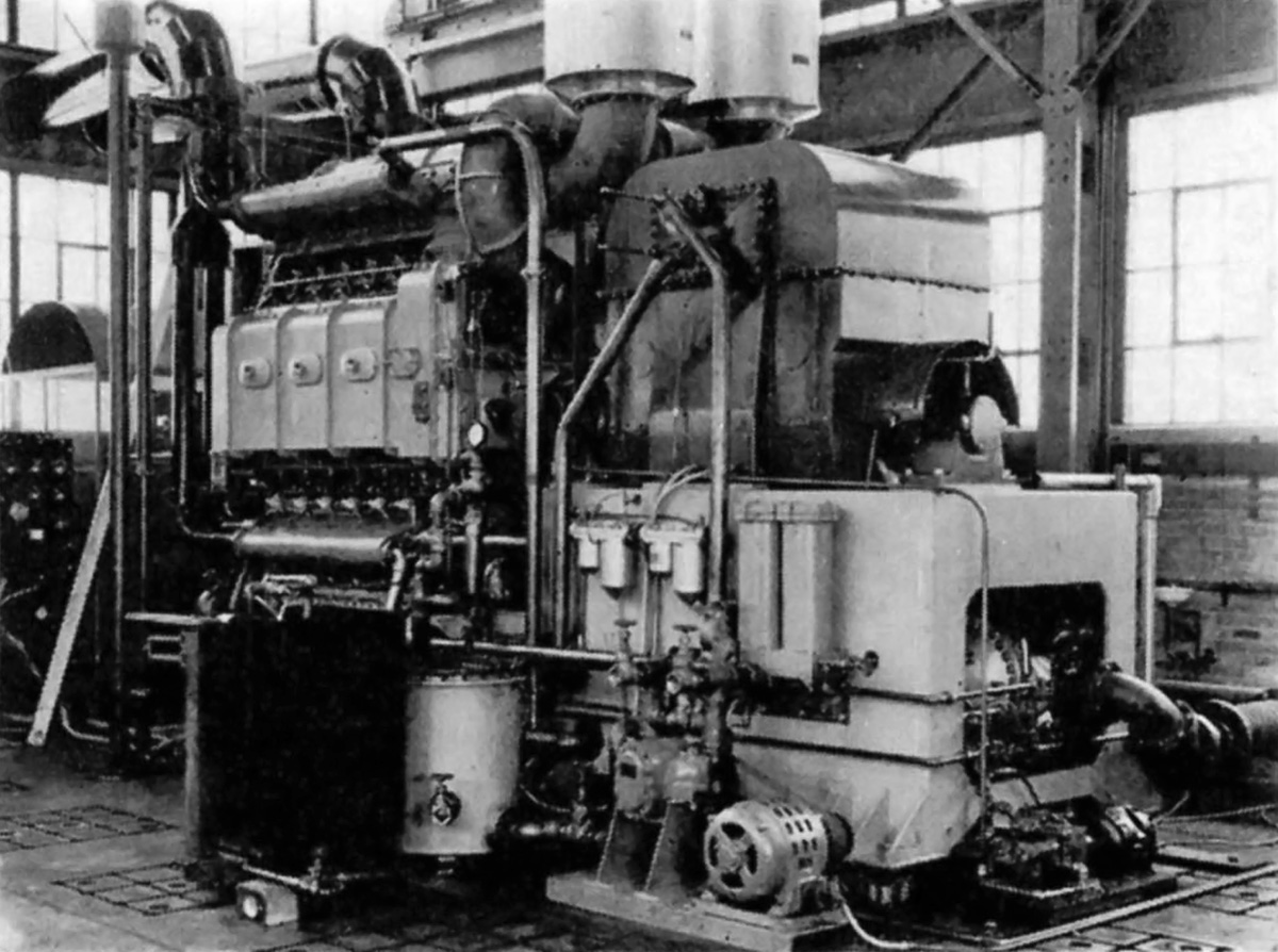
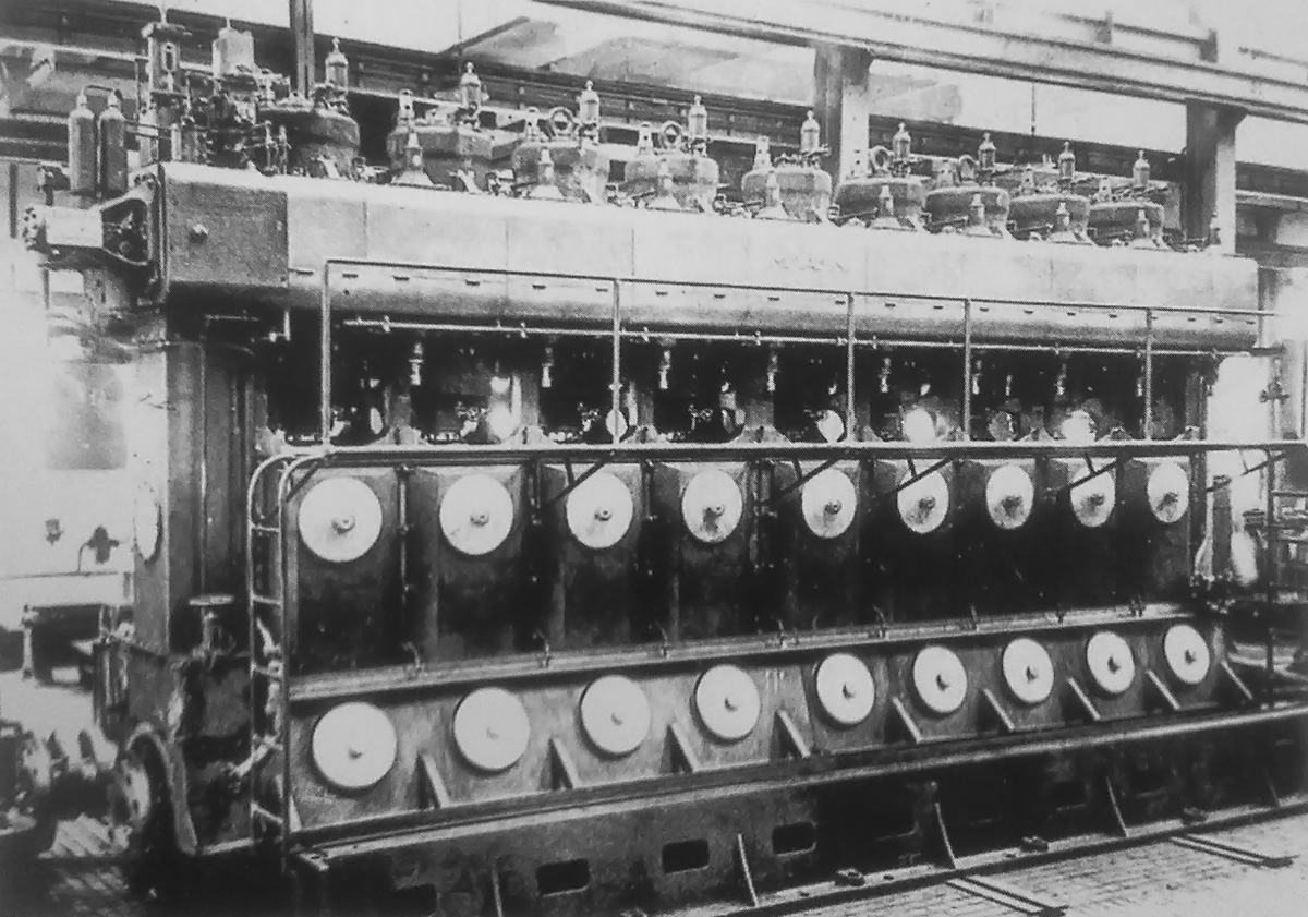
The Napier E130 three-cylinder test engine that validated the triangular engine arrangement. Each of the engine’s crankshafts had a flywheel on the drive end (left). The six intake chamber openings are visible on the free (non-drive) end (right). Note the vertical coolant pipes on top of the engine. (Napier/NPHT/IMechE images)

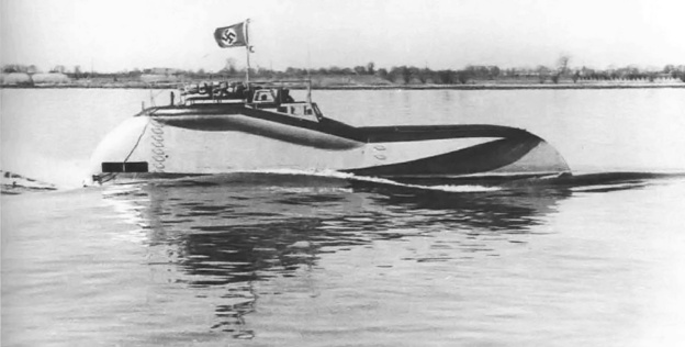
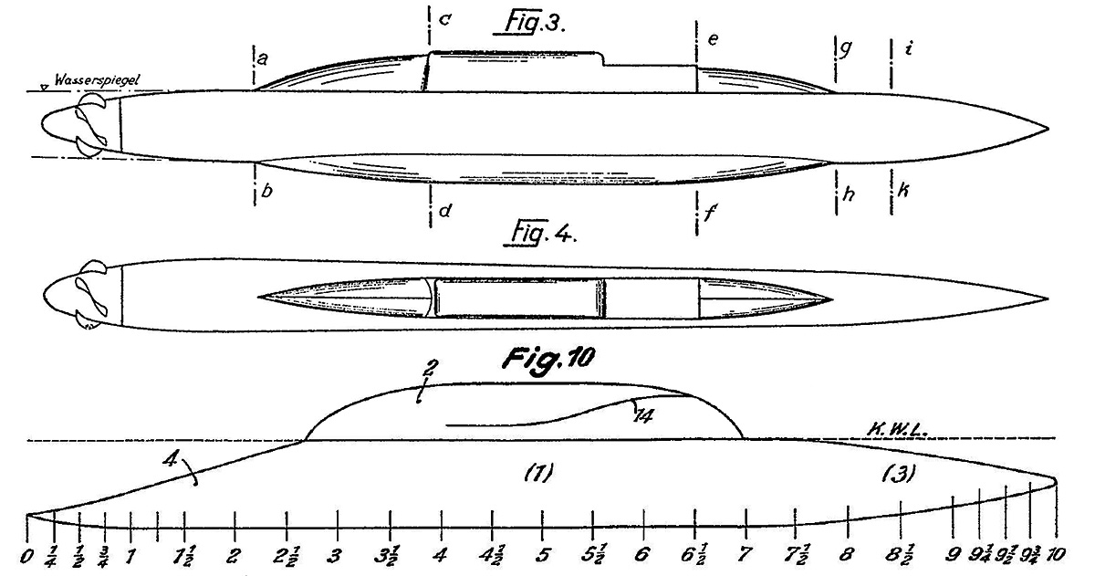
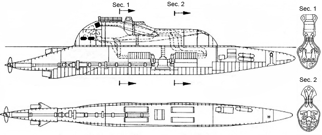
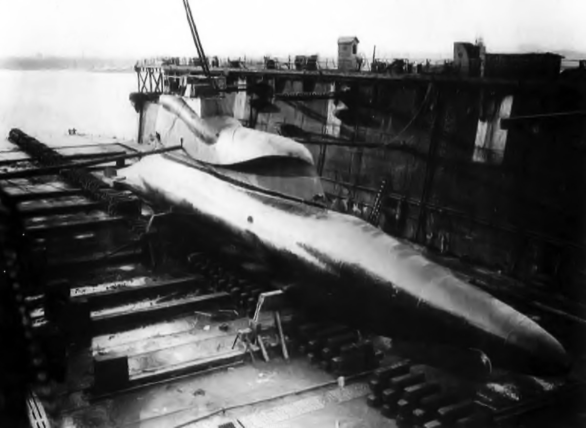
In 1944, the British Admiralty desired to increase the survivability of the Motor Torpedo Boat (MTB). One of the main issues was that MTBs used gasoline engines. Gasoline liquid is highly flammable, and gasoline vapor is highly explosive. MTB safety would be improved if a switch to diesel engines could be made. Diesel fuel has non-explosive characteristics and a much higher flashpoint than gasoline. However, at the time, there were no suitable diesel engines to power MTBs.

Around 1945, Napier and other companies submitted proposals to the Admiralty for a light-weight, powerful, and compact 18-cylinder diesel engine. Napier’s new engine carried the company designation E130, and the design was influenced by their experience with the Junkers Jumo diesel engines, their work on the Culverin and Cutlass, and analyses of other Jumo six-cylinder engines captured during World War II. However, there is no mention of the Junkers Jumo 223 contributing to Napier’s engine design. In early 1946, the Admiralty selected the Napier design and issued a developmental contract that covered the construction of one single-cylinder test engine, one three-cylinder test engine, and six prototype 18-cylinder engines.

Napier-Deltic-drive-end-section

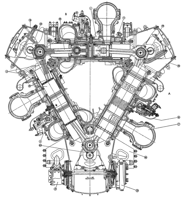
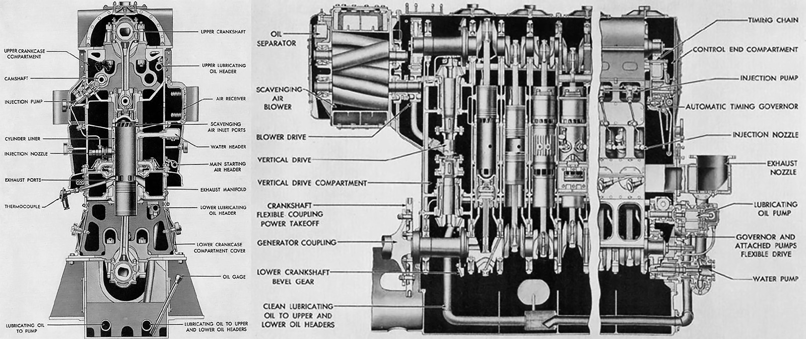
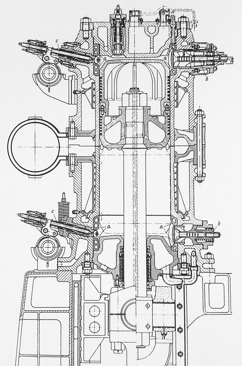
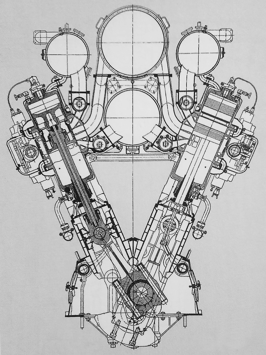
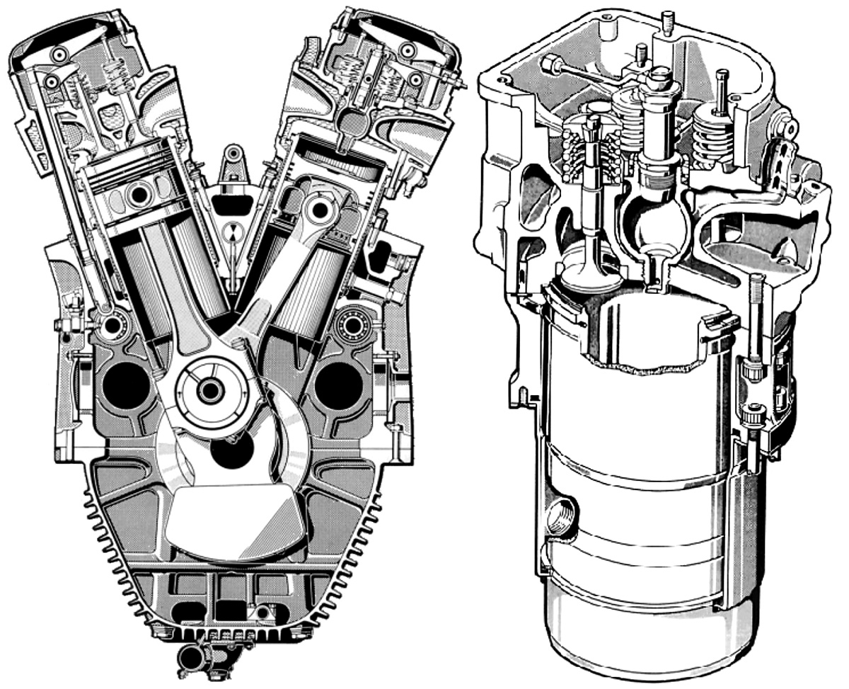
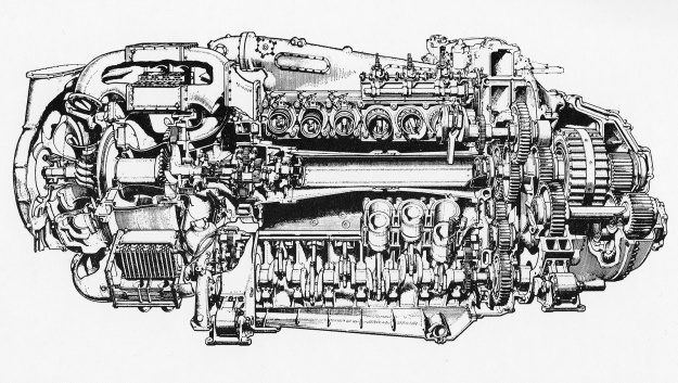
Section drawing from the drive end of a Deltic engine. The air chamber surrounds the intake end of the cylinder, and the exhaust manifolds are mounted to the outer sides of the engine. Note the rotation of the crankshafts. (Napier/NPHT/IMechE image)

Napier’s liquid-cooled, two-stroke engine used opposed-pistons, a design feature that eliminated many parts, required no cylinder head, improved thermal efficiency, and resulted in more power for a given size and weight. In an opposed-piston engine, each cylinder has two pistons that move toward each other to form a single combustion space near the center of the cylinder. Ports in the cylinder wall that are covered and uncovered by the pistons bring in air and allow exhaust gases to escape. The most unusual aspect of Napier’s design was that the engine was formed as an inverted triangle, with a crankshaft at each corner. Because of its triangular structure, the name Deltic was selected in reference to the Greek letter Delta, and the 18-cylinder engine was known as the Deltic D18 (or just 18). The triangular design resulted in a compact engine with a very rigid structure.

Design work on the Napier Deltic started under Ben Barlow, George Murray, and Ernest Chatterton, Chief Engineer of the Piston Engine Division at Napier. The project was initially overseen by Henry Nelson, with Herbert Sammons taking over in 1949. The Deltic engine formed an equilateral triangle with each of its three cylinder banks angled at 60 degrees. Cast aluminum crankcase housings were at each corner of the triangle, with the lower crankcase incorporating an oil sump and also serving as the engine’s base. Each cast aluminum cylinder bank was sandwiched between two crankcases via through bolts. The monobloc cylinder banks were identical, as were the upper two crankcases. However, various ancillary components were installed according to the casting’s position on the complete engine.

Napier-Deltic-18-Triangle-Case

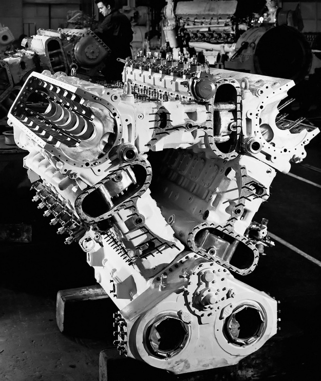
The assembled cylinder banks and crankcases of an 18-cylinder Napier Deltic engine seen from the free end. Note the open space between the cylinder banks. The stadium (oval) ports are to the air chambers. The bushings visible in the upper crankcases, at the triangle’s corners, supported the shafts that drove the blower. (Napier/NPHT/IMechE image)

The forged-steel cylinder wet liners were open-ended and had a chrome-plated bore to reduce wear. Part of the bore was etched with small dimples to retain lubricating oil and reduce piston ring wear. The liner was approximately 32 in (813 mm) long and protruded some distance into the crankcases. The ends of the liner were notched to allow clearance for the swinging connecting rods. Near one end of the liner were 14 intake ports with a tangential entry to impart a swirling motion of the incoming air. The swirling air helped scavenge the cylinder through the nine exhaust ports near the other end of the liner. In each cylinder, one piston would cover and uncover the intake ports while the other piston would do the same for the exhaust ports. The exhaust ports were uncovered (opened) 34.5 degrees before the intake ports. Both sets of ports were uncovered (open) for 101.5 degrees, and the intake ports were uncovered (open) for 5.5 degrees after the exhaust ports were covered (closed). The placement of the intake and exhaust ports at opposite ends of the cylinder liner allowed for uniflow scavenging of the cylinder. The liners were shrink-fitted into the cylinder banks and secured by an annular nut on the intake side.

The two-piece pistons consisted of a cast aluminum outer body and a forged Y-alloy (nickel-aluminum alloy) inner member that held the wrist pin. The inner member was heat-shrunk to the outer piston body and secured by a large circlip. Oil flowed between the two pieces to cool the piston. Three compression rings were positioned just below the piston crown, and two oil scraper rings were located near the bottom of the piston skirt. The pistons were attached to fork-and-blade connecting rods, with the exhaust pistons mounted to the forked rods and the intake pistons mounted to the blade rods. The opposed pistons created a compression ratio of 17.5 to 1 (some sources say 15 to 1).

Napier-Deltic-assembly

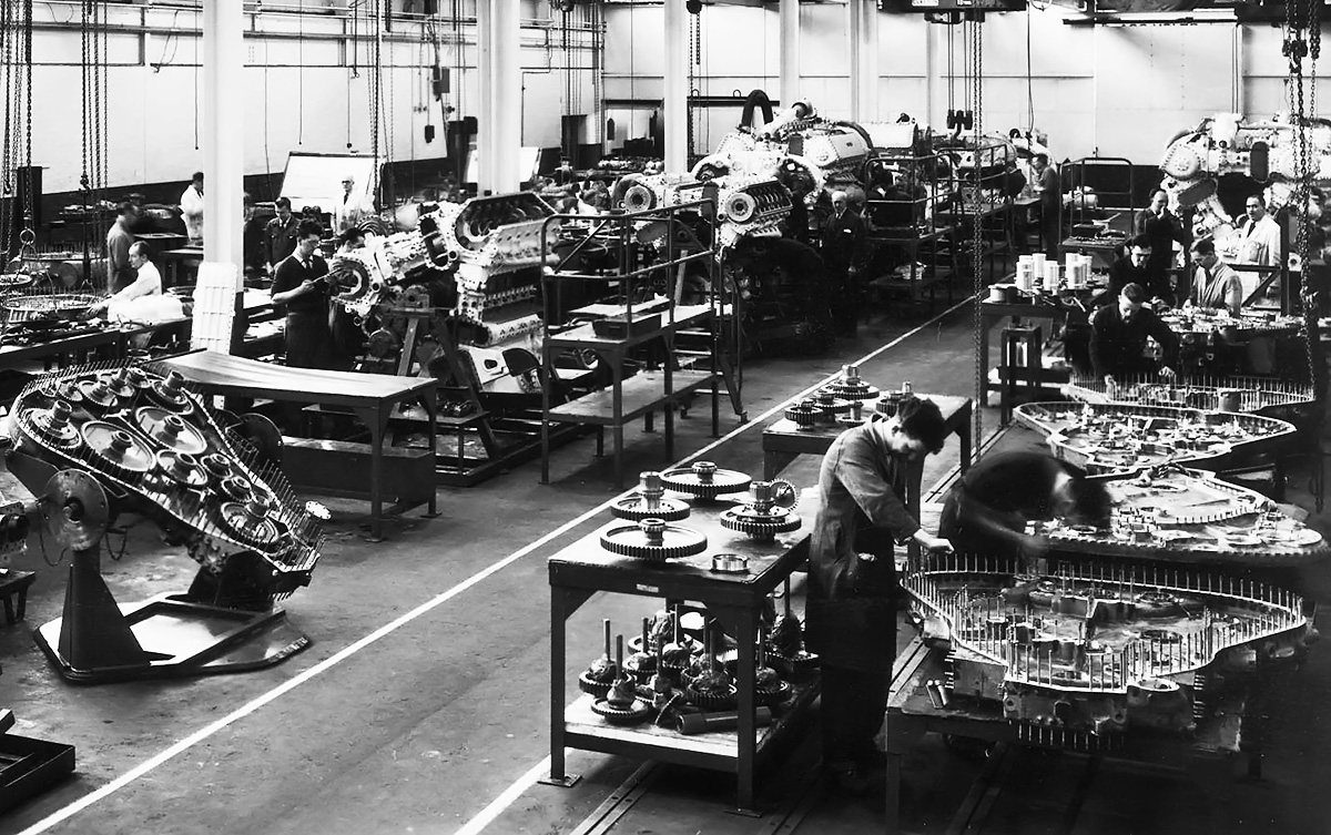
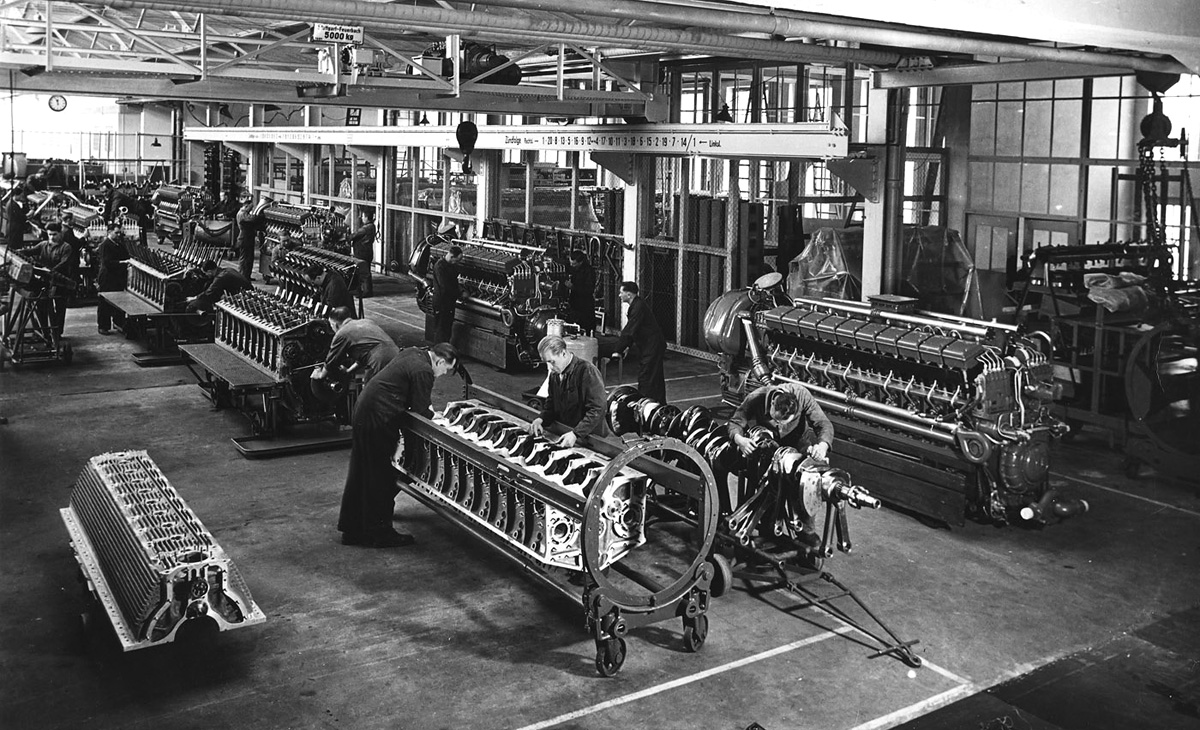
Napier Deltic engine assembly, with phasing gear housings being built up in the lower right. At left is a completed phasing gear housing; note the two idler gears connecting the lower crankshaft to the central output shaft. Toward the center are Deltics in various stages of assembly. A completed engine without its blower installed is in the upper right. Note the opening in the center of the engine. (Napier/NPHT/IMechE image)

A two-piece phasing gear housing at the drive end of the engine contained the gears that connected the crankshafts to the main output shaft. The main output shaft was usually located at the center of the engine, but different phasing gear housings allowed for different output shaft locations. Each crankshaft was coupled to its drive gear via a short, flexible quill shaft. When viewed from the free (non-drive) end of the engine, the upper two crankshafts rotated clockwise and were connected to the main output shaft via one idler gear. The lower crankshaft rotated counterclockwise and was connected to the main output shaft via two idler gears. The idler gears could be repositioned to reverse the rotation of the output shaft. Each crankshaft was supported in its crankcase by seven main bearings, and each main bearing cap was secured by four studs and two transverse bolts. The crankshafts were phased so that the exhaust piston in each cylinder led the intake piston by 20 degrees. The reverse rotation of the lower crankshaft, and the crankshaft phasing was devised by Herbert Penwarden from the Admiralty Engineering Laboratory.

Via a quill shaft and bevel gears, each crankshaft also drove a camshaft for the fuel injection pumps. The camshaft was located in a housing bolted to the outer side of each cylinder bank, near its center. Each camshaft operated six fuel injection pumps, and each pump fed fuel to two injectors per cylinder. The timing of the pumps changed depending on engine RPM. The upper two crankshafts drove separate flexible drive shafts for the blower (weak supercharger). The driveshafts were positioned at the upper, inner corners of the engine triangle. They led to the opposite end of the engine and powered a single-stage, double-sided centrifugal blower. The impeller was 15.5 in (394 mm) in diameter and rotated at 5.72 times crankshaft speed, creating 7.8 psi of boost (.53 bar). The pressurized air from the blower was fed into a chamber that extended through each cylinder bank and that surrounded the intake ports in the cylinder liner. Exhaust gases were collected via a water-cooled manifold that attached to the outer side of each cylinder bank. The lower crankshaft drove a flexible drive shaft to power the engine’s two oil and two water pumps.

Napier-Deltic-T18-37K-sections-display

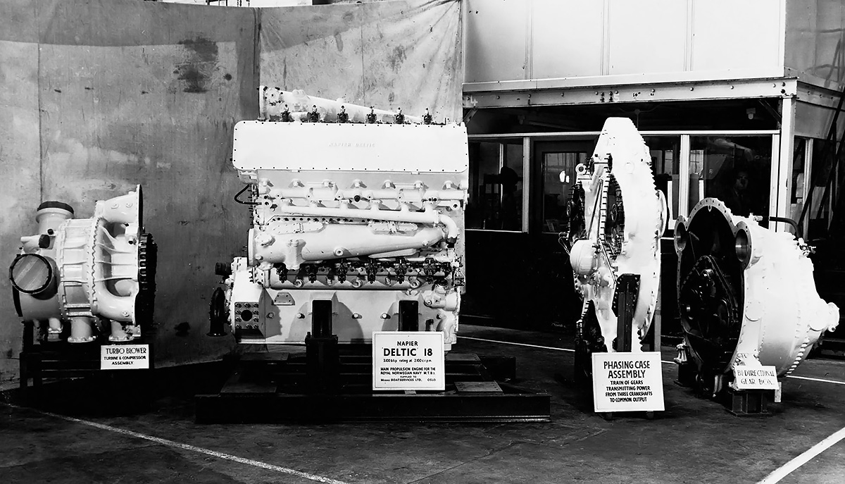
Basic sections of the Deltic (T18-37K) marine engine. From left to right are the blower section (turbo-blower in this case), D18-cylinder engine section, phasing gear housing, and the bi-directional gearbox. The Deltic was a powerful diesel engine for its size and weight. (Napier/NPHT/IMechE image)

When viewing the engine from the free end, the cylinder banks were designated as follows: left was Bank A; upper, horizontal was Bank B; and right was Bank C. The crankshafts were designated as follows: upper left was Crankshaft AB, upper right was Crankshaft BC, and lower was Crankshaft CA. The cylinder rows were numbered with Bank 1 at the free end, and subsequent banks were numbered consecutively with Bank 6 at the drive end. The Deltic D18’s firing order was Bank C cylinder 1 (C1), A6, B1, C5, A1, B5, C3, A5, B3, C4, A3, B4, C2, A4, B2, C6, A2, and B6.

The Napier Deltic had a 5.125 in (130 mm) bore and a 7.25 in (184 mm) stroke (x2). This gave each cylinder a displacement of 299 cu in (4.9 L), and the 18-cylinder engine displaced 5,384 cu in (88.2 L). The bare engine (without the bi-directional marine gearbox) had a maximum, 15-minute output of 2,730 hp (2,036 kW) at 2,000 rpm with a specific fuel consumption (sfc) of .380 lb/hp/hr (231 g/kW/h). The Deltic’s continuous rating was 2,035 hp (1,517 kW) at 1,700 rpm with a sfc of .364 lb/hp/hr (221 g/kW/h). With the bi-directional gearbox, the engine produced 2,500 hp (1,864 kW) at 2,000 rpm with a sfc of .415 lb/hp/hr (252 g/kW/h) and 1,875 hp (1,398 kW) at 1,700 rpm with a sfc of .395 lb/hp/hr (240 g/kW/h). The Deltic D18 was 105 in (2.67 m) long, 71.25 in (1.81 m) wide, and 80 in (2.03 m) tall. The bi-directional gearbox added another 36 in (.91 m). The engine weighed 8,860 lb (4,018 kg) without the bi-directional gearbox and 10,500 lb (4,763 kg) with it.

The single-cylinder test engine was designed from October to December 1946, with the three-cylinder engine following from January to May 1947. Testing of these engines started as soon as construction was completed. The three-cylinder engine represented just one row of a Deltic engine, but it demonstrated the validity of the components used in the triangular arrangement.

Napier-Deltic-D18-E130-Prototype

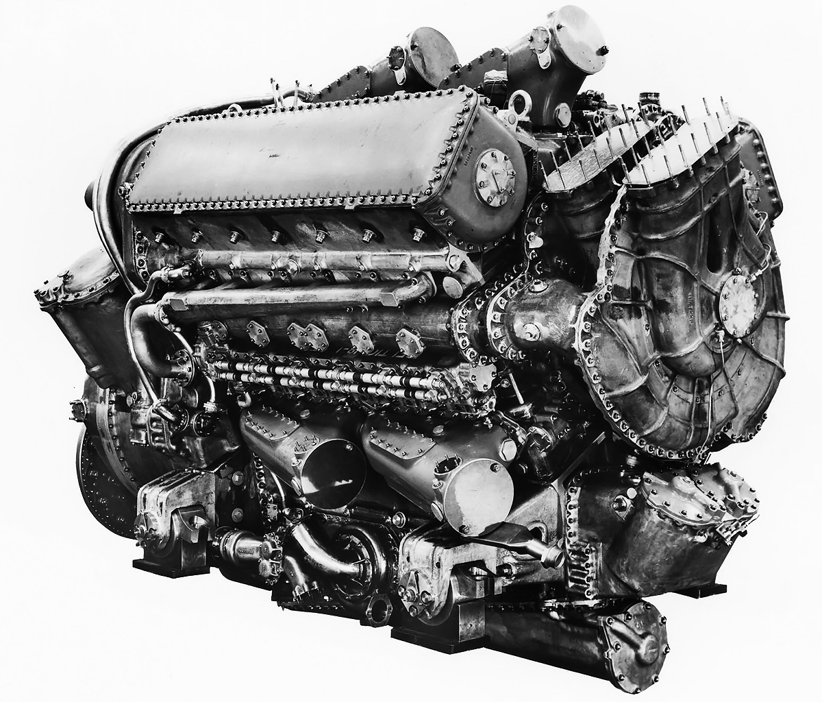
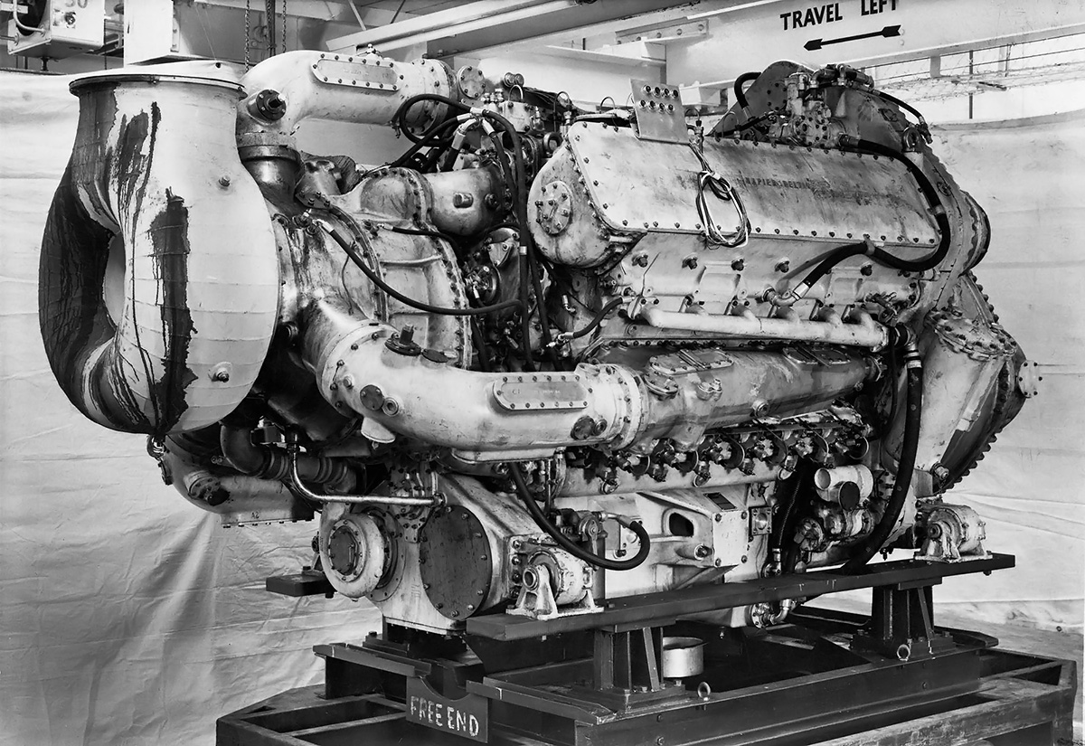
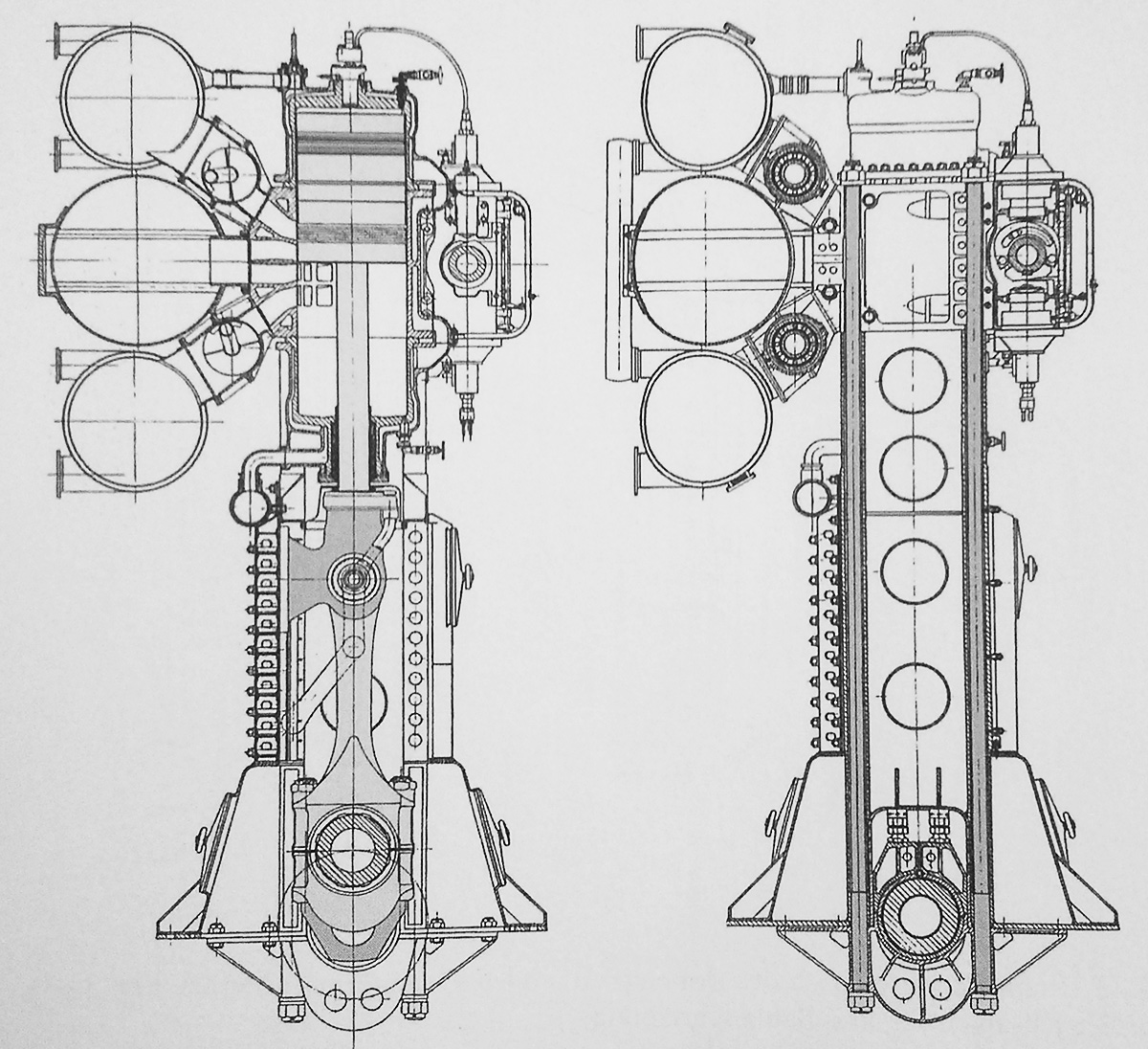
Free end of the 2,500 hp (1,864 kW) Deltic D18-1 (E130) prototype engine. Note the two intakes, one for each side of the double-sided blower. Each cylinder bank had two, large exhaust manifolds. The transverse bolts threaded into the main bearings can be seen on the side of the upper crankcase. (Napier/NPHT/IMechE image)

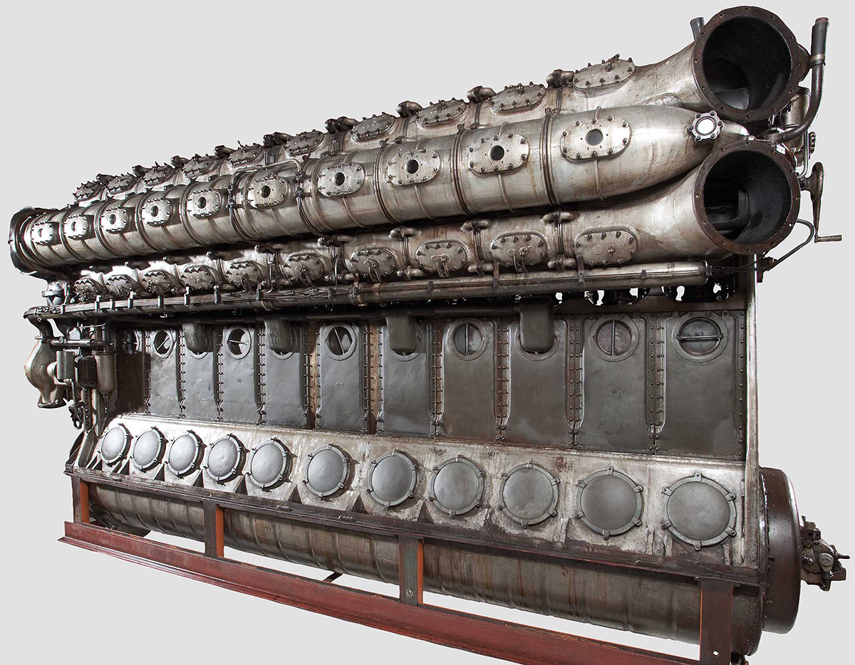
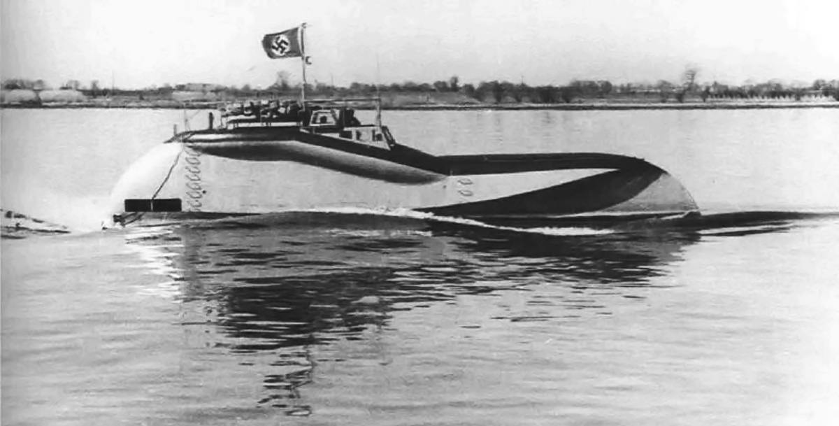
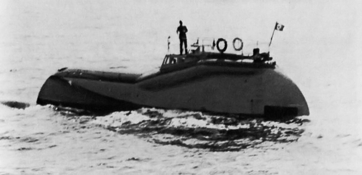
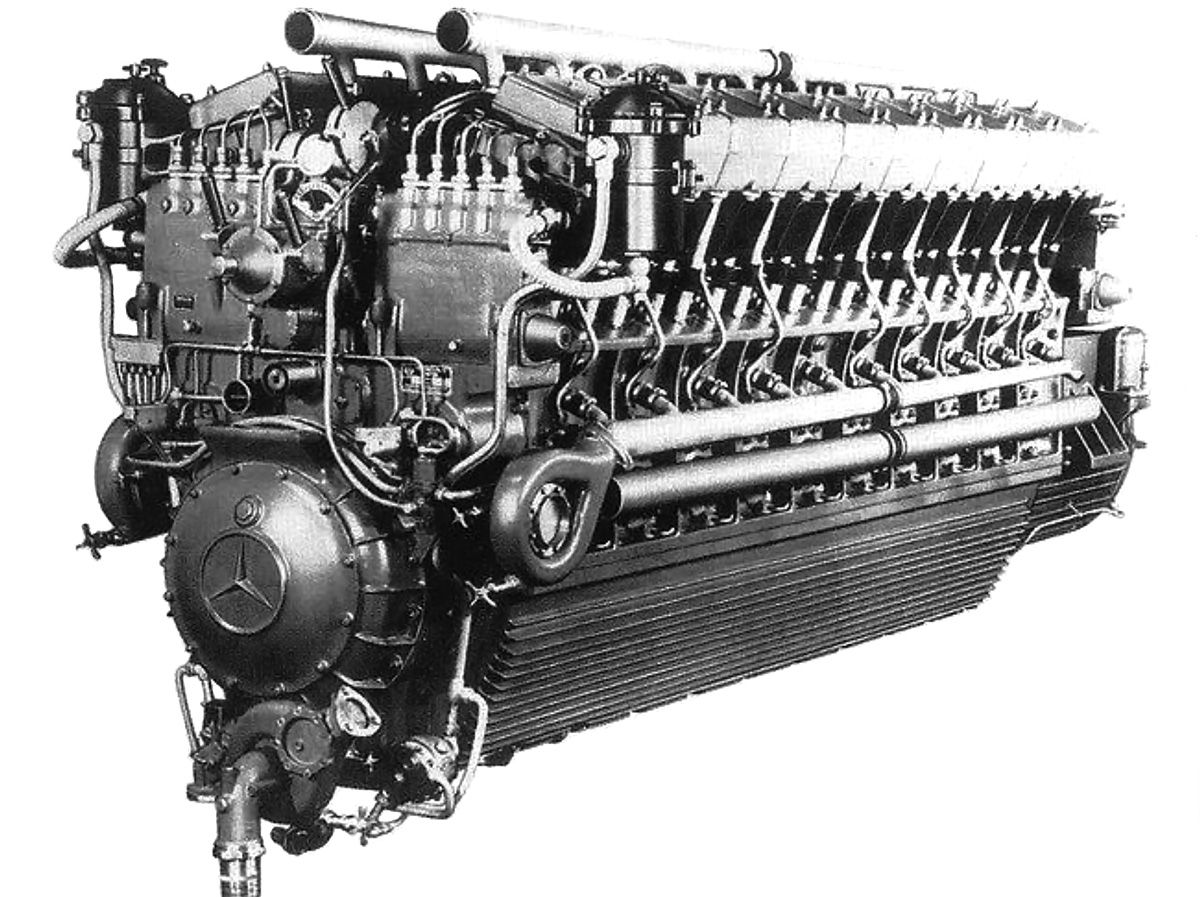
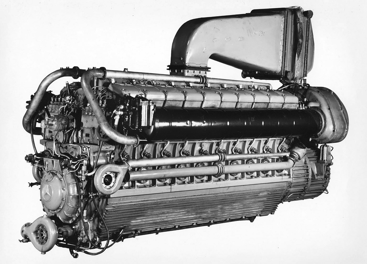
The first 18-cylinder Deltic Series I engine was assembled by March 1950. The engine was soon to be tested at Napier’s works in Acton, England; however, a cable broke as the engine was being mounted to the stand. It fell on the stand, damaging the engine and the test stand. Repairs were made, and engine began testing in April 1950. The 18-cylinder Deltic fired a cylinder every 20 degrees of crankshaft rotation, which resulted in smooth, nearly-constant output torque. Engine idle was around 600 rpm, and the Deltic demonstrated a gross mechanical efficiency of 85.5% at 2,000 rpm. In late 1951, two Deltics were installed in place of the three Mercedes-Benz MB 501 V-20 engines in a former German E-boat S-212 (redesignated Fast Patrol Boat P5212). By January 1952, the originally-contracted six Deltic D18 engines had been built. In 1953, an Admiralty 1,000-hr type test was completed and indicated the engine could run 2,000 hours between overhauls.

By 1954, Napier was offering a commercial version of the Deltic D18 Series I (E169). This was basically a de-rated engine. The commercial engine produced 1,900 hp (1,417 kW) at 1,500 rpm with a sfc of .363 lb/hp/hr (221 g/kW/h) and could operate for 5,000 hours between overhauls. In addition to a variety of marine applications, Deltic engines could also run power generation sets, water pumps, and be used to power traction motors for locomotives. Napier also built a nine-cylinder version with three banks of three cylinders. The Deltic 9 (E159/E165) displaced 2,692 cu in (44.1 L) and had a one-sided centrifugal blower but was otherwise of the same construction as the Deltic D18. It fired one cylinder for every 40 degrees of crankshaft rotation. Maximum output for the Deltic 9 was 1,250 hp (932 kW) at 2,000 rpm for the high-power version and 950 hp (708 kW) at 1,500 rpm for the commercial version. By late 1955, Deltic test and production engines had accumulated over 20,000 hours of operation.

Napier-Deltic-C18-5-Compound-Marine-Engine

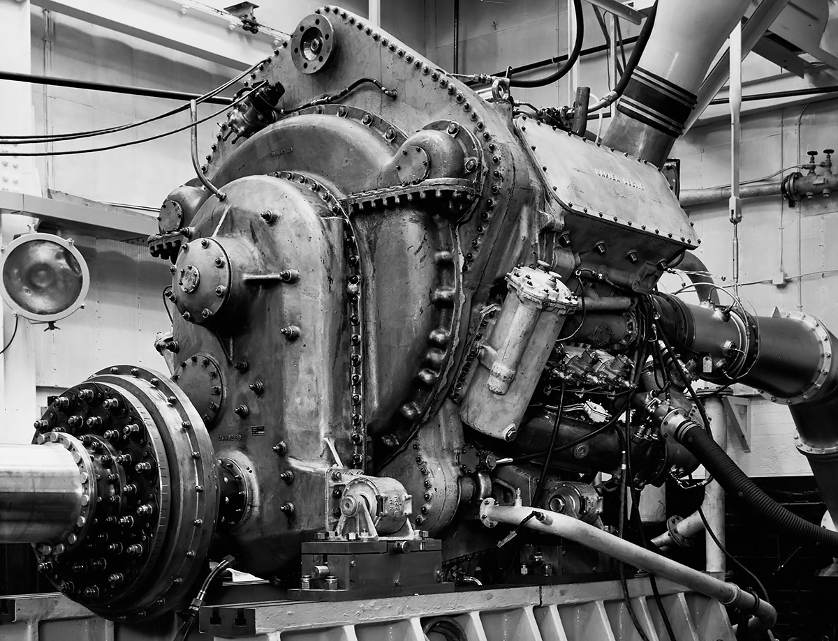
The 5,500 hp (4,101 kW) compound Deltic C18 (E185) engine was the most powerful piston engine Napier ever built. Although it is covered, the intake can be seen in the upper part of the phasing gear housing. Exhaust was routed through the three-stage turbine, which powered the eight-stage compressor inside the engine’s triangle. (Napier/NPHT/IMechE image)

In 1956, Napier built a compound diesel engine known as the Deltic C18 (E185). Serious development of the C18 occurred after the Napier Nomad II compound diesel aircraft engine was cancelled in 1955. The Deltic C18 had an eight-stage (some sources say 12-stage, which was the same number of stages as used in the Nomad II) axial compressor positioned inside the engine triangle. The compressor was driven by a three-stage turbine, which was powered by the engine’s exhaust gases. The turbine was positioned in the normal blower position on the free end of the engine. A new phasing gear housing was constructed with an opening that allowed air into the center of the engine triangle and served as the inlet for the compressor. The Deltic C18 produced 5,500 hp (4,101 kW) at 2,000 rpm. The engine was 124 in (3.15 m) long, 65 in (1.65 m) wide, and 77 in (1.96 m) tall. The C18 weighed approximately 10,700 lb (4,853 kg). The engine was tested in 1957, but only one experimental C18 was built. While undergoing power tests, the engine was intentionally pushed beyond its limits until a connecting rod failed at 5,600 hp (4,176 kW). The rod came through the crankcase, but the damage was never repaired due to the Navy’s increased focus on gas turbine engines.

By 1956, Napier had introduced some minor changes as the Series II Deltic engines, but one major change was the addition of a turbo-blower. These engines were known as turbo-blown, and they were designated as the Deltic T18 (E171/E239). Exhaust gases were collected and fed into an axial-flow turbine mounted behind the blower. The turbine wheel was 18.04 in (458 mm) in diameter and helped turn the blower via a geared shaft. The turbine wheel turned at .756 times the speed of the blower impeller. The blower was still driven by the upper crankshafts, but it now turned at 8.266 times crankshaft speed. The turbo-blower created 19 psi (1.31 bar) of boost. The piston was redesigned and consisted of three-pieces: a Hidural 5 (copper alloy) crown that screwed onto an aluminum skirt to form the outer body, and a Y-alloy (nickel-aluminum alloy) inner member that held the wrist pin. A third scraper ring was added to the piston skirt. The compression ratio was increased to 17.9 to 1, and the engine used one fuel injector per cylinder. The Deltic T18 had an output of 3,100 hp (2,312 kW) at 2,100 rpm and 2,400 hp (1,641 kW) at 1,800 rpm. SFC was .414 lb/hp/hr (252 g/kW/h) and .404 lb/hp/hr (246 g/kW/h) respectively. The engine was 118 in (3.00 m) long, 75 in (1.91 m) wide, and 84 in (2.13 m) tall. The T18 weighed around 13,630 lb (6,183 kg) with the bi-directional gearbox and 11,050 lb (5,012 kg) without it. The turbo-blown nine-cylinder Deltic T9 (E172/E198) produced 1,100 hp (820 kW) at 1,600 rpm.

Napier-Deltic-T18-37K-Marine-Engine

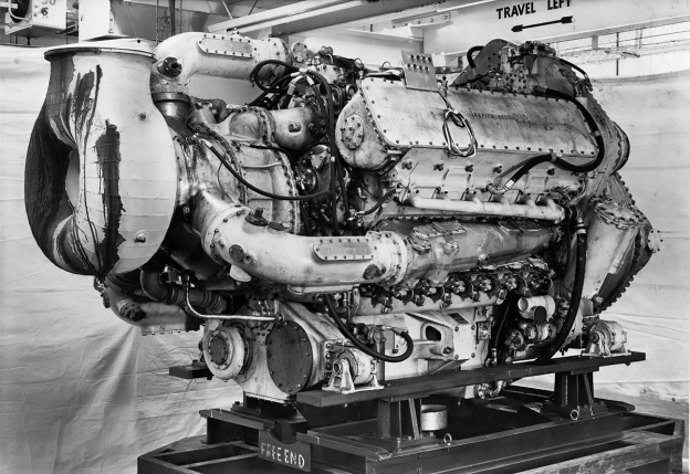
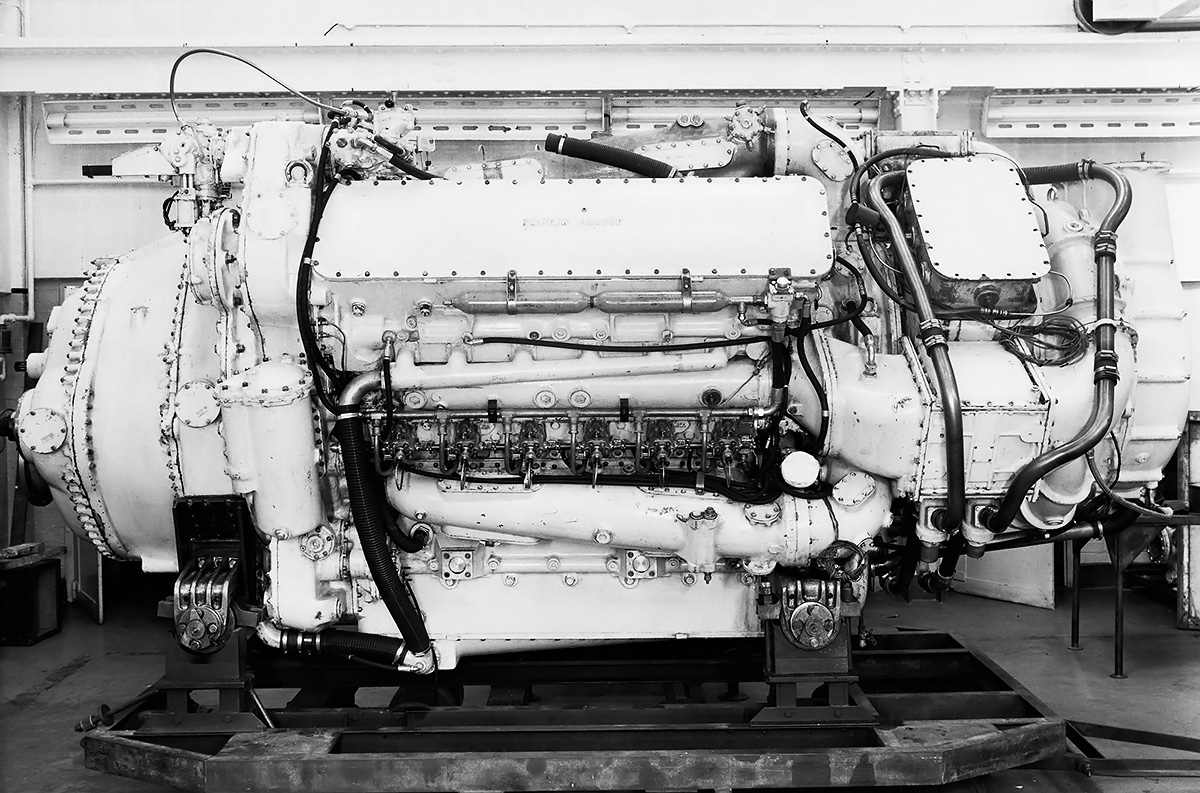
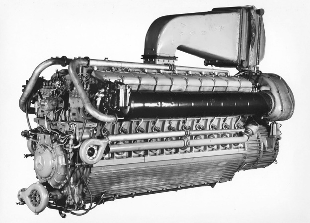
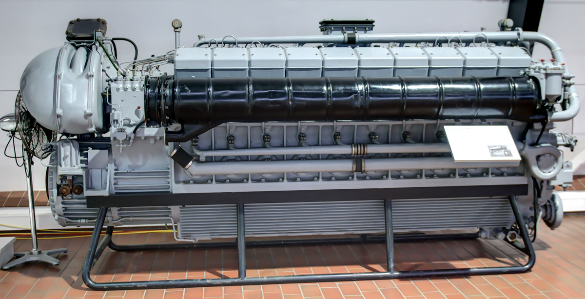
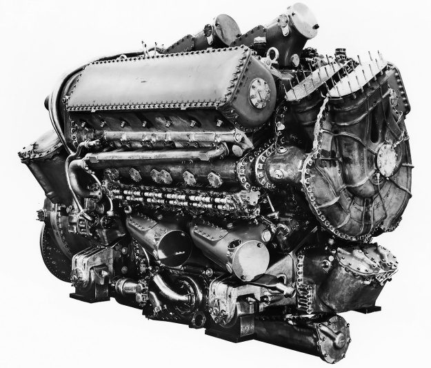
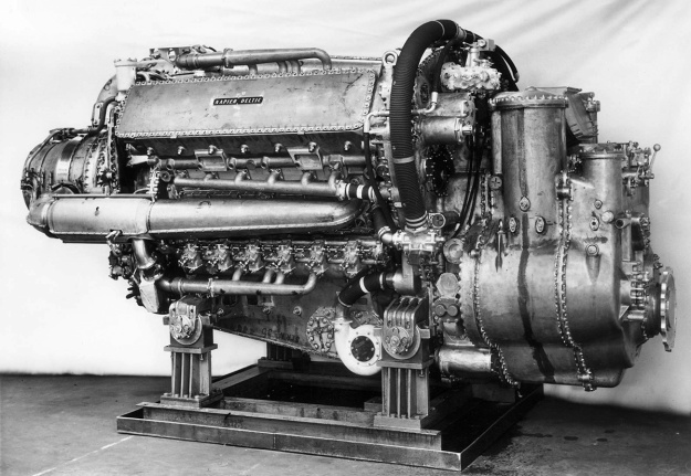
The 3,100 hp (2,312 kW) turbo-blown Deltic T18-37K (E239) engine was most widely used in Motor Torpedo Boats. Note the exhaust manifolds leading to the turbine with its large intake at the rear of the engine. The short duct connecting the blower to the upper cylinder bank is visible. (Napier/NPHT/IMechE image)

More changes were incorporated into the Series III engines, which also introduced charge-cooling with the Deltic CT18 (E263) in 1966. For the CT18, a single drive shaft passed through the center of the engine to deliver power from the phasing gear housing to the turbo-blower. The shaft turned at 5.16 times crankshaft speed, and both the blower impeller and turbine wheel were mounted to the drive shaft. The single-sided blower impeller was relocated to behind the turbine wheel. A water-filled aftercooler was mounted before each opening of the engine’s three air compartments. The aftercooler dropped the charge temperature from 259° F (126° C) to 144° F (62°C). Pistons were again redesigned, with the Hidural 5 (copper alloy) crown bolting to the aluminum skirt. For the Deltic CT18, power increased to 3,700 hp (2,759 kw) at 2,100 rpm with a sfc of .403 lb/hp/hr (245 g/kW/h) and 2,750 hp (2,051 kW) at 1,800 rpm with a sfc of .395 lb/hp/hr (240 g/kW/h). By 1968, further development had increased the output to 4,000 hp (2,983 kW) at 2,100 rpm with a sfc of .401 lb/hp/hr (244 g/kW/h) and 3,000 hp (2,237 kW) at 1,800 rpm with a sfc of .399 lb/hp/hr (243 g/kW/h). The CT18 weighed 15,382 lb (6,977 kg) with its bi-directional gearbox.

As Napier declined in the late 1960s, English Electric moved Deltic production to the newly acquired Paxman Engine Division. The General Electric Company (GEC, not related to the US company General Electric / GE) purchased English Electric in 1968. What was once Napier basically closed in 1969. In 1975, GEC reformed Paxman Engine Division as Paxman Diesels Limited. Paxman continued to support Deltic engines, developing the CT18 to 4,140 hp (3,087 kW) in 1978 and reworking the mechanically-blown Deltic 9 for production as the D9-59K (E280) in the early 1980s. The D9-59K was constructed almost entirely with non-ferrous (non-magnetic) parts for mine-sweeper duties. In 2000, MAN acquired what used to be Paxman, and Rolls-Royce was awarded a contract to support Deltic engines in 2001. The contract was carried through until 2012, but it is not clear if the contract was extended beyond that year.

Napier-Deltic-CT18-42K-Charge-Cooled-engine

A 3,700 hp (2,759 kw) charge-cooled and turbo-blown Deltic CT18-42K (E263) engine. The turbine is located between the engine and the blower. Note the large, square aftercooler in the air duct between the blower and the engine. (Napier/NPHT/IMechE image)

Deltic engines powered a number of various MTBs, including the Royal Navy’s Dark-class (18 produced). Two 3,100 hp (2,312 kW) Deltic C18 turbo-blown engines powered each Nasty-class / Tjeld-class fast patrol boat (total of 49 built), which were designed in 1959 and put in service in 1960. These boats served with the navies of Norway, the United States, Greece, Germany, and Turkey. The boats had a top speed of 52 mph (83 km/h), and some were in service until the 1990s. Deltic engines powered Ton-class minesweepers (over 100 built) as well as the pulse generators for other minesweepers. Deltics were still being installed in new military boats during the 1980s, with the 1,180 hp (880 kW) Deltic T9-powered Hunt-class minesweepers (13 built) still in service. A few commercial vessels were also powered by Deltic engines—the largest installation was four 1,850 hp (1,380 kW) engines for the 513.5-ft (156.5-m) ore carrier Bahama King in 1958.

In 1955, two 1,650 hp (1,230 kW) Deltic D18-12 (E158) engines were used in the English Electric DP1, a prototype diesel-electric locomotive. The engines powered six English Electric EE829-1A traction motors that gave the locomotive 50,000 lbf (222.4 kN) of tractive effort. The DP1 proved successful, resulting in 22 British Rail Class 55 locomotives powered by Deltic D18-25 (E169) engines being built in the early 1960s. Called Deltics, these locomotives could exceed 110 mph (177 km/h) and were in service until the early 1980s. One 1,100 hp (919 kW) Deltic T9-29 (E172) engine was used in each of the smaller British Rail Class 23 locomotives, known as Baby Deltics. The engine powered four English Electric traction motors that gave the locomotive 47,000 lbf (209.1 kN) of tractive effort. The Baby Deltics entered service in 1959, but they were not as successful as their bigger counterparts due to shorter runs and frequent stops. All Baby Deltics were withdrawn from service by 1971.

Napier-Deltic-CT18-Charge-Cooled-cutaway

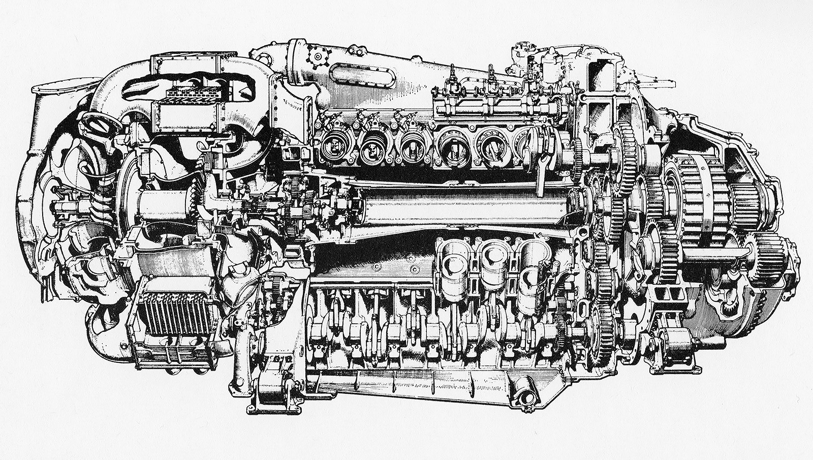
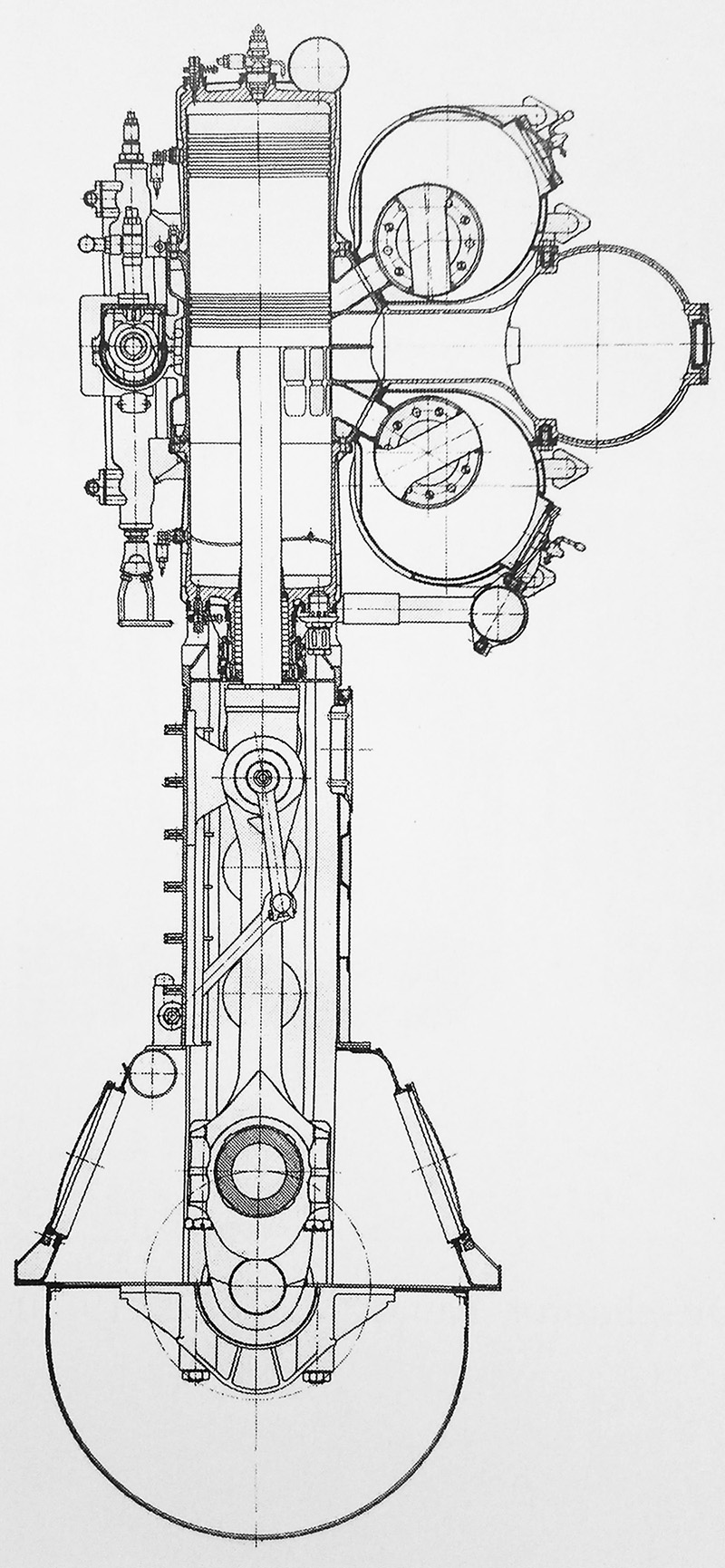
Cutaway view of a Deltic CT-18 charge-cooled and turbo-blown engine. Note the shaft through the center of the engine that powered the turbo-blower from the phasing gear. (Napier/NPHT/IMechE image)

Other Deltic designs included a 735 hp (548 kW) inline six-cylinder (E164/E197) with one bank of six cylinders and a 1,420 hp (1,059 kW) 15-cylinder (E162) with three banks of five cylinders, but these engines were not built. A 24-cylinder square engine (E260) with four crankshafts and four banks of six cylinders was also designed for an output of 5,400 hp (4,027 kW). The square engine design had much more in common with the Deltic than the Jumo 223, but it was not constructed. Including the nine-cylinder version, over 600 Deltic engines were made. A number of Deltic engines survive. Some are still operational in preserved boats or locomotives, allowing the unusual roar of the triangular two-stroke Deltic to still be heard. Others engines are in various museums, and a few are privately owned.

Note: In some cases, the Napier E number is one example of the type, with additional E numbers existing for similar engines with different configurations (marine vs rail applications). Around 100 E numbers were assigned to various Deltic designs.

Napier-Deltic-T9-33-Locomotive-Rraction-Engine

A 1,250 hp (932 kW) turbo-blown nine-cylinder Deltic T9-33 (E198) under test at Napier’s factory in Acton. The engine was similar to those used in the Baby Deltic Locomotives. Note the low position of the output shaft. (Napier/NPHT/IMechE image)

Sources:
– “The Napier Deltic Diesel Engine” by Ernest Chatterton, SAE Transactions Vol 64 (1956)
Opposed Piston Engines by Jean-Pierre Pirault and Martin Flint (2010)
Course Notes on the Deltic Engine Type T18-37K by D. Napier & Son Ltd. (December 1967)
– “Development of the Napier Deltic Charge Cooled Engine” by R. P. Taylor and C. H. Davison, Proceedings of the Institution of Mechanical Engineers Vol 183 (1968–69)
By Precision Into Power by Alan Vessey (2007)
Napier Powered by Alan Vessey (1997)
https://www.ptfnasty.com/ptfDeltic.html
http://www.npht.org/deltic/4579702653

Fairbanks Morse Diamond stress test

Fairbanks Morse Diamond Opposed-Piston Marine Engine

By William Pearce

In the early 1930s, Fairbanks Morse & Company (FM) took an interest in two-stroke, opposed-piston, diesel engines, and they acquired a license to produce a design originally developed by the German firm Junkers. In an opposed-piston engine, each cylinder has two pistons that move toward each other to form a single combustion space near the center of the cylinder. Ports in the cylinder wall bring in air and allow exhaust gases to escape. The opposed-piston design offers some advantages over conventional engines by having fewer parts, no cylinder head, improved thermal efficiency, and more power for a given size and weight.

Fairbanks Morse 38E 5.25

The Fairbanks Morse 38E5-1/4 had characteristics common to other 38-series opposed-piston engines and was a basis for the 24-cylinder Diamond engine. (Fairbanks Morse image)

FM used the information acquired from Junkers to develop its own line of opposed-piston diesel engines. One of the first opposed-piston engines produced by FM was the Model 38, which was a two-stroke vertical engine with two crankshafts linked initially by a gear train, which was soon replaced by a drive chain. In its 38A8 form, the engine had eight cylinders with an 8 in (203 mm) bore and a 10 in (254 mm) stroke (x2). The 38A8 displaced 8,042 cu in (131.8 L) and produced 1,200 hp (895 kW) at 720 rpm. In December 1934, the United States Navy ordered eight 38A8 engines—four each for the USS Plunger (SS-179) and USS Pollack (SS-180) Porpoise-class submarines. Problems with the 38A8s led to a redesign, ultimately creating the 38D8 engine.

In 1937, FM upgraded the 38D8 to produce more power. The drive chain linking the two crankshafts was replaced with a vertical shaft and bevel gears. The bore was increased by .125 in (3 mm) to 8.125 in (206 mm), and cylinders were added to create 9- and 10-cylinder engines. The new engine was designated 38D8-1/8. With the larger bore and 10 cylinders, the engine displaced 10,370 cu in (169.9 L) and produced 1,600 hp (1,193 kW) at 720 rpm. Approximately 1,650 38D8-1/8 engines were built during World War II. The engine was eventually offered with 4, 5, 6, 8, 9, 10, and 12 cylinders and with or without turbocharging. Although changes have been incorporated over the years, the FM OP 38D8-1/8 remains in production today.

In 1939, FM developed a scaled-down version of the 38D to be used as an auxiliary power unit. This engine was designated 38E5-1/4, and it had a 5.25 in (133 mm) bore and a 7.25 in (184 mm) stroke (x 2). The engine was available with three, five, or seven cylinders. The 7-cylinder 38E5-1/4 displaced 2,197 cu in (36.0 L) and produced 467 hp (348 kW) at 1,200 rpm. Around 630 38E5-1/4 engines were built during World War II.

Fairbanks Morse Diamond sectional

Sectional drawing of the Fairbanks Morse Diamond engine shows the arrangement of its four crankshafts and opposed-piston cylinders. The output shaft is drawn with a six-hole flange and is just below the center of the engine. (Fairbanks Morse image)

Based on the development of the Model 38-series, the Navy approached FM in early 1940 with a request to design and build a 3,000 hp (2,237 kW) opposed-piston engine for submarine use. With the prospect of war looming on the horizon, FM quickly went to work on the new engine design and assigned Robert Beadle as the program’s head engineer. The engine borrowed the basic cylinder design from the 38E5-1/4, but the engine was of a diamond configuration with a crankshaft at each corner. This gave the engine four banks of six opposed-piston cylinders resulting in a total of 24 cylinders.

The FM Diamond engine was of welded steel construction, with the crankcase and four cylinder banks forming a single unit. The lower and upper bank angles were 60 degrees. The left and right bank angles were 120 degrees. A cover concealed each crankshaft, and crankshaft removal allowed access to the cylinder liners. Each forged steel crankshaft was supported by seven main bearings.

The fork-and-blade connecting rods were made from steel forgings and then polished for added strength. The rods were drilled to deliver oil from the crankshaft to the wrist pin and to the underside of the piston crown for cooling. The pistons had a concave crown and formed a somewhat hemispherical combustion space when the two pistons came together. The two-piece pistons were made of cast steel with an aluminum wrist pin carrier.

The cylinder liners were made of forged steel and had a chrome-plated bore. A water jacket was pressed on each liner’s center section, where combustion occurred. Intake and exhaust ports were cast into the cylinder liners, and movement of the pistons covered and uncovered these ports. The upper and lower crankshafts were connected to the “exhaust” pistons that controlled the exhaust ports, and the left and right crankshafts operated the “intake” pistons controlling the intake ports. The crankshafts were phased so that the exhaust pistons (upper and lower crankshafts) led the intake pistons (left and right crankshafts) by about 15 degrees. This allowed for good cylinder scavenging, with the exhaust ports being uncovered (open) before the intake ports and with the intake ports remaining uncovered (open) for a short time after the exhaust ports had been covered (closed).

Fairbanks Morse Diamond stress test

The welded crankcase of the Diamond engine undergoing stress tests before final assembly. The crankshafts and pistons are installed, and the output shaft is visible just below the engine’s center. Note the mounting pads at the top of the engine for the two centrifugal blowers. The blowers fed air into the center of the engine via the two large holes. (Fairbanks Morse image)

The upper crankshaft drove two gear-driven centrifugal blowers (weak superchargers) mounted to the drive end of the engine. The blowers forced air into a central chest inside of the engine diamond. Four compartments, one for each bank, surrounded the intake end of the cylinders and supplied air from the chest. The intake ports in the cylinder liner were tangentially cast so that the incoming air initiated a swirling motion as it entered the cylinder. This swirl helped scavenge the cylinder of exhaust gases and mix the fuel once it was injected. The exhaust end of each cylinder was surrounded by an open passageway that led outside of the engine. A water-cooled exhaust manifold made of welded steel was attached to the side of the engine and collected the exhaust gases.

Each of the left and right crankshafts drove an upper and lower camshaft. The camshafts actuated individual fuel injector pumps for the single fuel injector in each cylinder. The fuel injector was located in the center of the cylinder liner. Fuel was injected into the cylinder at approximately 3,000 psi (207 bar). All of the crankshafts were geared to a single output power shaft, located 13.75 in (349 mm) below the engine’s absolute center. The left, right, and lower crankshafts were each connected to the output shaft via one idler gear. The upper crankshaft was geared to the output shaft through three idler gears. The gears used herringbone teeth. Pressurized air fed through internal piping was used to start the engine.

In designing the engine, FM engineers spent over 6,000 man-hours on torsional vibration calculations alone. The FM Diamond engine was completed in 1942. It had a 5.25 in (133 mm) bore and a 7.25 in (184 mm) stroke (x 2). The engine’s total displacement was 7,533 cu in (123.4 L). The engine was 120 in (3.05 m) tall and 72 in (1.83 m) wide when bare, or 141.5 in (8.73 m) tall and 79.25 in (24.16 m) wide when mounted to its steel stand. Its length was approximately 90 in (27.43 m).

During testing, the Diamond engine produced 3,000 hp (2,237 kW) at 1,500 rpm with 6.88 psi (.47 bar) of scavenging pressure. At this power, the specific fuel consumption was .420 lb/hp/hr (255 g/kW/h). However, the engine experienced constant issues with excessive wear and carbon build-up in the intake and exhaust ports. The program was cancelled at the end of World War II. At the time of cancellation, the experimental Diamond engine had accumulated 2,032 hours of test running.

Fairbanks Morse Diamond test stand

The engine undergoing bench tests. Note the two centrifugal blowers providing air for scavenging and combustion. (Fairbanks Morse image)

Sources:
– “Development of Diamond Opposed-Piston Diesel Engine” by R. H. Beadle (discussion of “The Napier Deltic Diesel Engine”) SAE Transactions Vol 64 (1956)
Opposed Piston Engines by Jean-Pierre Pirault and Martin Flint (2010)
Diesels for the First Stealth Weapon: Submarine Power 1902–1945 by Lyle Cummins (2007)
Submarine Main Propulsion Diesels: NavPers 16161 (June 1946)
http://www.dieselduck.info/machine/01%20prime%20movers/fairbanks_morse/fairbanks_morse.htm

Isotta Fraschini Asso 750 front

Isotta Fraschini W-18 Aircraft and Marine Engines

By William Pearce

In late 1924, the Italian firm Isotta Fraschini responded to a Ministero dell’Aeronautica (Italian Air Ministry) request for a 500 hp (373 kW) aircraft engine by designing the liquid-cooled, V-12 Asso 500. Designed by Giustino Cattaneo, the Asso 500 proved successful and was used by Cattaneo as the basis for a line of Asso (Ace) engines developed in 1927. Ranging from a 250 hp (186 kW) inline-six to a 750 hp (559 kW) W-18, the initial Asso engines shared common designs and common parts wherever possible.

Isotta Fraschini Asso 750 front

The direct drive Isotta Fraschini Asso 750 was the first in a series of 18-cylinder engines that would ultimately be switched to marine use and stay in some form of production for over 90 years.

The Isotta Fraschini Asso 750 W-18 engine consisted of three six-cylinder banks mounted to a two-piece crankcase. The center cylinder bank was in the vertical position, and the two other cylinder banks were spaced at 40 degrees from the center bank. The cylinder bank spacing reduced the 18-cylinder engine’s frontal area to just slightly more than a V-12.

The Asso 750’s crankcase was split horizontally at the crankshaft and was cast from Elektron, a magnesium alloy. A shallow pan covered the bottom of the crankcase. The six-throw crankshaft was supported by eight main bearings. On each crankshaft throw was a master rod that serviced the center cylinder bank. Articulating rods for the other two cylinder banks were mounted on each side of the master rod. A double row ball bearing acted as a thrust bearing on the propeller shaft and enabled the engine to be installed as either a pusher or tractor.

The individual cylinders were forged from carbon steel and had a steel water jacket that was welded on. The cylinders had a closed top with openings for the valves. The monobloc cylinder head was mounted to the top of the cylinders, with one cylinder head serving each bank of cylinders. The cylinder compression ratio was 5.7 to 1. The cylinder head was made from cast aluminum and held the two intake and two exhaust valves for each cylinder. The valves were actuated by dual overhead camshafts, with one camshaft controlling the intake valves and the other camshaft controlling the exhaust valves (except for the center bank). A single lobe on the camshaft acted on a rocker and opened the two corresponding valves for that cylinder. The camshafts for each cylinder bank were driven at the rear of the cylinder head. One camshaft of the cylinder bank was driven via beveled gears by a vertical drive shaft, and the second camshaft was geared to the other driven camshaft. The valve cover casting was made from Elektron.

Isotta Fraschini Asso 750 RC35 crankcase

The cylinder row, upper crankcase, and cylinder head (inverted) of an Asso 750 RC35 with gear reduction. The direct drive Asso 750 was similar except for the shape of the front (right side) of the crankcase. Note the closed top cylinders. The small holes between the studs in the cylinder top were water passageways that communicated with ports on the cylinder head.

Three carburetors were mounted to the outer side of each outer cylinder bank. The intake and exhaust ports of the outer cylinder banks were on the same side. The intake and exhaust ports of the center cylinder bank were rather unusual. When viewed from the rear, the exhaust ports for the rear three cylinders of the center bank were on the right, and the intake ports were on the left. The front three cylinders were the opposite, with their exhaust ports on the left and their intake ports on the right. This configuration gave the cylinders for the center bank crossflow heads, but it also meant that each camshaft controlled half of the intake valves and half of the exhaust valves. A manifold attached to the inner side of the left cylinder bank collected the air/fuel mixture that had flowed through passageways in the left cylinder head and delivered the charge to the rear three cylinders of the center bank. The right cylinder bank had the same provisions but delivered the mixture to the front three cylinders of the center bank. Presumably, the 40-degree cylinder bank angle did not allow enough room to accommodate carburetors for the middle cylinder bank.

The two spark plugs in each cylinder were fired by two magnetos positioned at the rear of the engine and driven by the camshaft drive. From the rear of the engine, the firing order was 1 Left, 6 Center, 1 Right, 5L, 2C, 5R, 3L, 4C, 3R, 6L, 1C, 6R, 2L, 5C, 2R, 4L, 3C, and 4R. A water pump positioned below the magnetos circulated water into a manifold along the base of each cylinder bank. The manifold distributed water into the water jacket for each individual cylinder. The water flowed up through the water jacket and into the cylinder head. Another manifold took the water from each cylinder head to the radiator for cooling. Starting the Asso 750 was achieved with an air starter.

Motore Isotta Fraschini Asso 750

Two views of the direct drive Asso 750 displayed at the Museo nazionale della scienza e della tecnologia Leonardo da Vinci in Milan. Note the three exhaust stacks visible on the center cylinder bank. The front image of the engine illustrates the lack of space between the cylinder banks, which were set at 40 degrees. (Alessandro Nassiri images via Wikimedia Commons)

The Isotta Fraschini Asso 750 had a bore of 5.51 in (140 mm), a stroke of 6.69 in (170 mm), and a total displacement of 2,875 cu in (47.1 L). The original, direct drive Asso 750 produced 750 hp (599 kW) at 1,600 rpm, and weighed 1,279 lb (580 kg). An improved version of the Asso 750 was soon built that produced 830 hp (619 kW) at 1,700 rpm and 900 hp (671 kW) at 1,900 rpm. This engine weighed 1,389 lb (630 kg). The direct drive Asso 750 was 81 in (2.06 m) long, 40 in (1.02 m) wide, and 42 in (1.07 m) tall.

A version of the Asso 750 with a spur gear reduction for the propeller was developed and was sometimes referred to as the Asso 850 R. Available gear reductions were .667 and .581, and the gear reduction resulted in the crankshaft having only seven main bearings. The Asso 850 R produced 850 hp (634 kW) at 1,950 rpm, and weighed 1,455 lb (660 kg). This engine was also further refined and given the more permanent designation of Asso 750 R. The 750 R had a .658 gear reduction. The engine produced 850 hp (634 kW) at 1,800 rpm and 930 hp (694 kW) at 1,900 rpm. The Asso 750 R was 83 in (2.12 m) long and weighed 1,603 lb (727 kg).

Isotta Fraschini Asso 750 rc35 front

Front view of the Asso 750 RC35. The gear reduction required new upper and lower crankcase halves and a new crankshaft, but the other components were interchangeable with the direct drive engine.

Around 1933 the Asso 750 R engine was updated to incorporate a supercharger. The new engine was designated Asso 750 RC35. The “R” in the engine’s designation meant that it had gear reduction (Riduttore de giri); the “C” meant that it was supercharged (Compressore); and the “35” stood for the engine’s critical altitude in hectometers (as in 3,500 meters). The engine’s water pump was moved to a new mount that extended below the oil pan. The supercharger was mounted between the water pump and the magnetos, which were moved to a slightly higher location. The supercharger was meant to maintain sea level power up to a higher altitude, and it provided .29 psi (.02 bar) of boost up to 11,483 ft (3,500 m). The Asso 750 RC35 produced 870 hp (649 kW) at 1,850 rpm at 11,483 ft (3,500 m). The engine was 87 in (2.20 m) long, 41 in (1.03 m) wide, 48 in (1.21 m) tall, and weighed 1,724 lb (782 kg).

In 1928, Isotta Fraschini designed a larger, more powerful engine that had both its bore and stroke increased by .39 in (10 mm) over that of the Asso 750. The larger engine was developed especially for the Macchi M.67 Schneider Trophy racer. The M.67’s engine was initially designated Asso 750 M (for Macchi) but was also commonly referred to as the Asso 2-800. The “2” designation was most likely applied because the engine was a “second generation” and differed greatly from the original Asso 750 design.

Isotta Fraschini Asso 750 rc35 rear

The single-speed supercharger on the Asso 750 RC35 is illustrated in this rear view. Note the relocated and new mounting point for the water pump. The supercharger forced-fed air to the engine’s six carburetors.

The Asso 2-800 had a bore of 5.91 in (150 mm), a stroke of 7.09 in (180 mm), and a total displacement of 3,434 cu in (57.3 L). The engine used new crossflow cylinder heads and a new crankcase. The cylinder heads had intake ports on one side and exhaust ports on the other. Air intakes for the engine were positioned behind the M.67’s spinner, with one intake on the left side for the left cylinder bank and two intakes on the right side for the center and right cylinder banks. Ducts delivered the air to special carburetors positioned between the cylinder banks. The modified engine also had a higher compression ratio and used special fuels. Under perfect conditions, the special Asso 2-800 engine produced up to 1,800 hp (1,342 kW), but it was rarely able to achieve that output. An output of 1,400 hp (1,044 kW) was more typical and still impressive. At speed, the Asso 2-800 in the M.67 reportedly made a roar like no other engine.

Isotta Fraschini made a commercial version of the larger engine, designated Asso 1000. With the same bore, stroke, and displacement as the Asso 2-800, the Asso 1000 is often cited as the engine powering the M.67. However, the Asso 1000 retained the same configuration and architecture as the Asso 750, except the Asso 1000 had a compression ratio of 5.3 to 1. Development of the Asso 1000 trailed slightly behind that of the Asso 750.

The direct drive Isotta Fraschini Asso 1000 produced 1,000 hp (746 kW) at 1,600 rpm and 1,100 hp (820 kW) at 1,800 rpm. The engine was 86 in (2.19 m) long, 42 in (1.06 m) wide, and 44 in (1.12 m) tall. The Asso 1000 weighed 1,764 lb (800 kg). Like with the original Asso 750, a gear reduction version was designed. This engine was sometimes designated as the Asso 1200 R. The gear reduction speeds available were .667 and .581. The Asso 1200 R produced 1,200 hp (895 kW) at 1,950 rpm and weighed 2,116 lb (960 kg).

Isotta Fraschini Asso 1000

The Isotta Fraschini Asso 1000 was very similar to the Asso 750. Note the intake manifolds between the cylinder banks, each taking the air/fuel mixture from one of the outer banks and feeding half of the center bank.

The Asso 750 and Asso 1000 engines were used in a variety of aircraft, but most of the aircraft were either prototypes or had a low production count. For the Asso 750, its most famous applications were the single engine Caproni Ca.111 reconnaissance aircraft (over 150 built) and the twin engine Savoia-Marchetti S.55 double-hulled flying boat. Over 200 S.55s were built, but only the S.55X variant was powered by the Asso 750. Twenty-five S.55X aircraft were built, and in 1933, 24 S.55X aircraft made a historic formation flight from Orbetello, Italy to Chicago, Illinois. The Asso 750 powered many aircraft to numerous payload and distance records. Six direct-drive Asso 1000 engines were used to power the Caproni Ca.90 bomber, which was the world’s largest landplane when it first flew in October 1929. The Ca.90 set six payload records on 22 February 1930.

Although not a complete success in aircraft, the Asso 1000 found its way into marine use as the Isotta Fraschini ASM 180, 181, 183 and 184 engines. ASM was originally written as “As M” and stood for Asso Marini (Ace Marine). The marine engines had water-cooled exhaust pipes and a reversing gearbox coupled to the propeller shaft. The Isotta Fraschini marine engines were used in torpedo boats before, during, and after World War II by Italy, Finland, Sweden, and Britain. Some of the engines and boats remained in service into the mid-1960s.

Isotta Fraschini ASM 184

The Isotta Fraschini ASM 184 engine with its large, water-cooled exhaust manifolds and drive gearbox. Note that the center bank only has its rear (left) cylinders feeding into the visible exhaust manifold. One of the two centrifugal superchargers can be seen at the rear of the engine. The engine is on display at the Museo Nicolis in Villafranca di Verona. (Stefano Pasini image)

The ASM 180 and 181 were developed around 1933, and produced 900 hp (671 kW) at 1,800 rpm. Refinement of the ASM 181 led to the ASM 183, which produced 1,150 hp (858 kW) at 2,000 rpm. Development of the ASM 184 started around 1940; it was a version of the ASM 183 that featured twin centrifugal superchargers mounted to the rear of the engine. The ASM 184 engine produced 1,500 hp (1,119 kW) at 2,000 rpm. Around 1950, production of the ASM 184 was continued by Costruzione Revisione Motori (CRM) as the CRM 184. In the mid-1950s, the engine was modified with fuel injection into the supercharger compressors and became the CRM 185. The CRM 185 produced 1,800 hp (1,342 kW) at 2,200 rpm.

CRM continued development of the W-18 platform and created a diesel version of the engine. Designated 18 D, the engine retained the same bore, stroke, and basic configuration as the Asso 1000 and earlier ASM engines. However, the 18 D was made of cast iron, had revised cylinder heads, and had a compression ratio of 14 to 1. The revised cylinder head was much taller and incorporated extra space between the valve springs and the valve heads. The valve stems were elongated, and a pre-combustion chamber was positioned between the valve stems and occupied the extra space in the head. Some versions of the engine have a fuel injection pump consisting of three six-cylinder distributors driven from the rear of the engine, while other versions have a common rail fuel system.

CRM 18 D engines

Four CRM 18 D engines, which can trace their heritage back to the Asso 1000. The three engines on the left use mechanical fuel injection with three distribution pumps. The engine on the right has a common fuel rail. Note the three turbochargers at the front of each engine. (CRM Motori image)

The exhaust gases for each bank were collected and fed through a turbocharger at the front of the engine (some models had just two turbochargers). Pressurized air from the turbochargers passed through an aftercooler and was then fed into two induction manifolds. Each of the manifolds had three outlets. The front and rear outlets were connected to the outer cylinder bank, and the middle outlet was connected to the center bank. For the center bank, induction air for the rear three cylinders was provided by the left manifold, and the front three cylinder received their air from the right manifold.

Various versions of the 18 D were designed, the most powerful being the 18 D BR3-B. The BR3-B had a maximum output of 2,367 hp (1,765 kW) at 2,300 rpm and a continuous output of 2,052 hp (1,530 kW) at 2,180 rpm. The engine had a specific fuel consumption of .365 lb/hp/hr (222 g/kW/h). The BR3-B was 96 in (2.45 m) long, 54 in (1.37 m) wide, 57 in (1.44 m) tall, and weighed 4,740 lb (2,150 kg) without the drive gearbox. CRM, now known as CRM Motori Marini, continues to market 18 D engines.

Isotta Fraschini Asso L180

Other than having a W-18 layout, the Isotta Fraschini L.180 did not share much in common with the Asso 750 or 1000. However, the two-outlet supercharger suggests a similar induction system to the earlier engines. Note the gear reduction’s hollow propeller shaft and the mounts for a cannon atop the engine.

In the late 1930s, Isotta Fraschini revived the W-18 layout with an entirely new aircraft engine known as the Asso L.180 (or military designation L.180 IRCC45). The Asso L.180 was an inverted W-18 (sometimes referred to as an M-18) that featured supercharging and a propeller gear reduction. The engine’s layout and construction were similar to that of the earlier W-18 engines. One source states the cylinder banks were spaced at 45 degrees. With nine power pulses for each crankshaft revolution, this is off from the ideal of having cylinders fire at 40-degree intervals (like the earlier W-18 engines) and may be a misprint. The crankshaft was supported by seven main bearings in a one-piece aluminum crankcase. The spur gear reduction turned at .66 crankshaft speed and had a hollow propeller shaft to allow an engine-mounted cannon to fire through the propeller hub. The single-speed supercharger turned at 10 times crankshaft speed.

The Isotta Fraschini L.180 had a 5.75 in (146 mm) bore and a 6.30 in (160 mm) stroke. The engine displaced 2,942 cu in (48.2 L) and had a compression ratio of 6.4 to 1. The L.180 had a takeoff rating of 1,500 hp (1,119 kW) at 2,360 rpm, a maximum output of 1,690 hp (1,260 kW) at 2,475 rpm at 14,764 ft (4,500 m), and a cruising output of 1,000 hp (746 kW) at 1,900 rpm at 14,764 ft (4,500 m). It is doubtful that the L.180 proceeded much beyond the mockup phase.

A number of Isotta Fraschini aircraft and marine engines are preserved in various museums and private collections. Some marine engines are still in operation, and the German tractor pulling group Team Twister uses a modified Isotta Fraschini W-18 engine in its Dabelju tractor.

Dabelju IF W-18 57L

The modified Isotta Fraschini W-18 in Team Twister’s Dabelju. The engine’s heads have been modified to have individual intake and exhaust ports. These crossflow heads are similar in concept to the heads used on the Macchi M.67’s engine. (screenshot of Johannes Meuleners Youtube video)

Sources:
Isotta Fraschini Aviation (undated catalog, circa 1930)
Isotta Fraschini Aviation (1929)
Isotta Fraschini Aviazione (undated catalog, circa 1931)
Istruzioni per l’uso del motore Isotta-Fraschini Tipo Asso 750 (1931)
Istruzioni per l’uso del motore Isotta-Fraschini Tipo Asso 750 R (1934)
Istruzioni per l’uso del motore Isotta-Fraschini Tipo Asso 750 RC 35 (1936)
Istruzioni per l’uso del motore Isotta-Fraschini Tipo Asso 1000 (1929)
Aeronuatica Militare Museo Storico Catalogo Motori by Oscar Marchi (1980)
Aircraft Engines of the World 1941 by Paul H. Wilkinson (1941)
Jane’s All the World’s Aircraft 1931 by C. G. Grey (1931)
https://www.t38.se/marinens-motortyper-i-mtb/
http://www.crmmotori.it/interna.asp?tema=16

timossi-verga laura 3 front

Timossi-Verga Laura 3 Hydroplane

By William Pearce

Mario Verga was a successful silk merchant born in Milan, Italy in 1910. In the late 1940s, he became a well-known Italian speedboat racer, competing in the 450 kg (992 lb) class. He left boat racing in 1950 when he married Liliana Burlazzi, but the pull of the sport was too strong for Verga to stay away.

abbate-verga laura i

The Abbate-built Laura I was a sleek design. Aluminum bodywork covered the Alfa Romeo Typo 159 engine. Note the step between the sponson and the hull.

In 1952, Verga returned to the speedboat world with his 450 kg (992 lb) class Laura I racer. Named after Verga’s young daughter, the boat was built by Guido Abbate at Lake Como and was 17 ft 3 in (5.25 m) long and 7 ft 6 in (2.28 m) wide. The Laura I was powered by an Alfa Romeo Typo (Type) 159 engine, the same type of engine that propelled auto racing legends Nino Farina and Juan Manuel Fangio to respective Formula 1 World Championships in 1950 and 1951. The “a” after the number in the boat’s name designated the Alfa Romeo engine. Verga and the Laura I captured the 450 kg (992 lb) class championship in 1952.

On 7 July 1952, and half the world away on Lake Washington’s East Channel near Mercer Island in the Pacific Northwest, Stanley Sayres and Elmer Leninschmidt set a new world absolute water speed record at 178.497 mph (287.263 km/h) in the three-point hydroplane Slo-mo-shun IV. Sayres, Ted Jones, and Slo-mo-shun IV had set the previous record at 160.323 mph (258.015 km/h) on 26 June 1950, the first post-World War II water speed record. For both records, Slo-mo-shun IV was powered by an Allison V-1710 engine.

timossi-verga laura ii

The Laura II used the same bodywork as the Laura I. However, the sponsons had no step between them and the hull, and the hull had larger fuel tanks. Note the engine’s eight exhaust stacks.

Modifications to Laura I had increased the boat’s weight, and it fell within the 800 kg (1,764 lb) class. On 29 January 1953, Verga set an 800 kg (1,764 lb) class speed record of 125.670 mph (202.247 km/h) in Laura I. He increased the record to 140.737 mph (226.495 km/h) on 15 February 1953. Both records were set on Lake Lugano.

Verga had a new 800 kg (1,764 lb) class boat built by Carlo Timossi at Lake Como. The new boat was named Laura II, and it was 17.5 ft (5.33 m) long and powered by the same Typo 159 engine that powered Laura I. Images indicate that the aluminum bodywork of Laura I was used on Laura II. Verga and the Laura II won the 800 kg (1,764 lb) class championship in Europe on October 1953 and then traveled to the United States. The Laura II won the Orange Bowl International Regatta Grand Prix held at Miami Beach, Florida in December 1953, and also set a speed record for the 151 cu in (2.47 L) hydroplane class, averaging 131.680 mph (211.919 km/h).

Verga’s speed records and the records of other Italian speedboat racers (Achille Castoldi averaged 150.188 mph / 241.704 km/h in the 800 kg class, Ferrari-powered Arno XI on 15 October 1953 at Lake Iseo) inspired the Italian Motornautical Federation to offer a £5,000,000 prize to the sportsman that surpassed Slo-mo-shun’s 178.497 mph (287.263 km/h) record. Stipulations for the prize were that the boat had to be made in Italy, powered by an Italian engine using Italian fuel, and driven by an Italian driver. Verga and a couple of other Italian racers accepted the challenge. However, the other contenders soon dropped out as complications were encountered.

timossi-verga laura 3 engines

The two Typo 159 engines mounted in their frame, as the frame is installed in the Timossi-built Laura 3. The two-stage Roots-type supercharger can be seen on the front engine. Note the propeller shaft extending below the rear engine.

For the water speed record challenge, Vega turned to Timossi for a specially-built boat, named Laura 3. Verga continued with the Typo 159 power plant but decided to use two of the engines. The Typo 159 design stemmed from the Alfa Romeo Typo 158, originally designed in 1937. Commonly called an Alfetta, for Little Alfa, the engine was a straight-eight that used a one-piece aluminum cylinder head and block mounted to a magnesium alloy crankcase. The cylinders had a 2.28 in (58 mm) bore and a 2.76 in (70 mm) stroke, making the engine’s total displacement 90 cu in (1.48 L). The Typo 159 employed a two-stage Roots-type supercharger that enabled the engine to produce an impressive 420 hp (313 kW) at 9,300 rpm.

The two Typo 159 engines were positioned back-to-back, with a 2-into-1 gearbox positioned between the engines. Combined, the engines produced over 800 hp (597 kW). The gearbox increased input speed so that the propeller shaft turned at 1.133 times engine rpm. The engines and gearbox were mounted in a special, tubular-steel frame built by Alfa Romeo. The wooden Laura 3 was a three-point hydroplane built around the steel power train frame, which was installed in the front of the boat. Aluminum body panels covered the engines and cockpit. Extending behind the cockpit was an aluminum tail that had a ground adjustable rudder for stability. The Laura 3 was 23 ft 7.5 in (7.20 m) long and 8 ft .5 in (2.45 m) wide. The boat weighed 2,028 lb (920 kg).

timossi-verga laura 3 hoist

The completed Laura 3 was an elegant hydroplane. Note the tail extending behind the cockpit. The rudder on the tail was ground-adjustable, and its angle could not be changed while the boat was in motion.

In July 1954, Verga and the Laura 3 made a series of test runs up to 100 mph (160 km/h) on Lake Pusiano. The boat was then moved to the larger Lake Iseo. The testing continued in August, and 165 mph (265 km/h) was reached. Verga made a record attempt on 28 August, hitting 170 mph (274 km/h), but a cooling issue was encountered that resulted in damage to one of the engines. Repairs were made, and testing resumed in September. At higher speeds, Verga fought against the boat’s tendency to pull to the left, but was unable to keep the Laura 3 traveling in a straight line. Efforts to correct the issue had been unsuccessful, and it was decided that modifications to the hull were needed before a record attempt could be made safely. Changes to both sponsons were made, and the boat was completed on 8 October.

timossi-verga laura 3 top

Top view of the Laura 3 illustrates the long bodywork needed to enclose the two Typo 159 engines. Note the eight exhaust stack on both sides of the cowling. The writing behind the cockpit reads Bi Motore Alfa Romeo 159 Scarfo Timossi, with “scafo” meaning “hull.”

Although full testing of the modifications had not been conducted, Verga was confident that Laura 3 could break Slo-mo-shun IV’s record. On 9 October 1954, Verga had waited until midday for the Il Trvano wind to die down over Lake Iseo and settle its waters, but the wind persisted. Verga decided to make a run anyway. As Verga and the Laura 3 sped over Lake Iseo at a speed of approximately 190 mph (305 km/h), the boat hit a couple of small waves that raised its bow. At speed, the aerodynamic forces caught the bow and lifted the Laura 3 out of the water. The boat flipped and rolled before smashing back down into Lake Iseo and sinking. Verga was instantly killed in the crash, and the Laura 3 was destroyed. Verga’s run in the Laura 3 was the last time an Italian tried to set an absolute world water speed record.

timossi-verga laura 3 front

The beautiful Laura 3 sits ready for a test run. Note the individual induction scoops for the Typo 159 engines.

In 2015, the Laura I was restored by Tullio Abbate, Guido’s son, with a non-original (2.5 L Alfa Romeo V-6) engine installed. The boat is on display at the Museo della Barca Lariana on Lake Como. The fate of the Laura II is not known. The tail of Laura 3 was salvaged and preserved.

Note: As previously mentioned, the Laura I and Laura II used the same aluminum bodywork. The boats were very similar but had different sponsons. Some sources state that Laura II set the 800 kg record in 1953. However, newsreel footage and the museum housing the preserved Laura I credit the Laura I with the record.

timossi-verga laura 3 front 2

Mario Verga prepares to make a run in Laura 3. Note the “Mario Verga” text on the front of the boat.

Sources:
Risk Takers and Record Breakers by Doug Ford (2012)
Classic Racing Engines by Karl Ludvigsen (2001)
– “The Glorious Obsession of Mario Verga” by David Tremayne, Veloce via www.lesliefield.com
– “Aqua Romeo!” by Doug Nye, Motor Sport (February 2013)
– “Southward Ho!” by Solly Hall, Motor Boating (December 1953)
http://www.vintagehydroplanes.com/boats/laura_3/laura3.html
https://www.threepointhydroplanes.it/abbate-guido-1953-62_c140_en.htm
https://www.threepointhydroplanes.it/timossi-1953-1_c229_en.htm
https://www.threepointhydroplanes.it/timossi-1954-1_c230_en.htm

MAN 6-cyl WWI

MAN Double-Acting Diesel Marine Engines

By William Pearce

Maschinenfabrik Augsburg-Nürnberg (MAN) was involved with diesel engines since their inception. From 1893 to 1897, MAN* worked with Rudolf Diesel to develop his combustion cycle and build the first diesel engines. When Diesel’s engine first ran in 1894, it produced around 3 hp (2 kW) at 88 rpm. Just 15 years later, MAN was contracted to develop a diesel engine capable of 12,000 hp (8,948 kW) at 120 rpm.

MAN 6-cyl WWI

The MAN six-cylinder, double-acting, two-stroke, 12,000 hp, diesel marine engine under construction. The three workers provide a good reference as to the engine’s size.

The remarkable rise of diesel power caught the eye of many militaries. Anton von Rieppel, general manager of MAN at Nürnberg (Nuremberg), felt that diesels had matured enough to power the latest battleships. In August 1909, Rieppel proposed a new engine to the Reichsmarine (Germany Navy). By late 1909, a development contract was issued to MAN for the construction of a 12,000 hp (8,948 kW), six-cylinder diesel engine. Six of the engines would be needed to produce the 70,000 hp (52,199 kW) required for the latest German battleships. Given the uncharted territory MAN was traversing, a three-cylinder engine would be built first to prove that a six-cylinder engine could meet the desired specifications. Other companies were also contracted to build competing engines.

MAN’s design was an inline, two-stroke engine that used double-acting cylinders. Each of the closed cylinders had a combustion chamber at its top and bottom. Originally, each combustion chamber had four intake valves, four fuel valves, and two safety valves that were also used for air-starting the engine. The safety valves were located at the center of the combustion chamber. The locations of the remaining valves were split between passageways that branched off from either side of the upper combustion chamber. With the exception of the safety valves, the valves for each side of each combustion chamber were actuated by a single underhead camshaft. This configuration had a total of 20 valves for each cylinder and four camshafts for the engine. The final (seventh) combustion chamber design retained the four intake valves but had only two fuel valves and one safety valve (located in the upper combustion chamber). The changes lowered the number of valves per cylinder to 15. Exhaust ports were located in the middle of the cylinder and were covered and uncovered by the piston.

MAN 6-cyl section

A drawing of the final cylinder design of the World War I engine. Fuel valves are on the left of the drawing, and intake valves are on the right. The exhaust manifold is positioned at the center of the cylinder. Note how the two piston halves are bolted together.

The double-headed piston was constructed of two parts. The lower part was connected to a non-articulating piston rod, and the upper part of the piston was bolted to the lower part. The piston rod was connected to the connecting rod via a cross head. The cross head slid in vertical channels on both sides of the inner crankcase. Oil was circulated through the piston to cool it. The oil flowed up through passageways in the piston rod and into the lower part of the piston. The oil then flowed to the upper part of the piston and down the center of the piston rod. The upper and lower combustion chamber sections were bolted to the center section of the cylinder, and the assembly was attached to the crankcase. A water jacket surrounded the cylinder. The center section of the cylinder and of the upper combustion chamber were made of cast iron. The crankcase, piston, lower combustion chamber, and many other components were made of cast steel. Each complete cylinder assembly was around 12 ft (3.5 m) tall, and the engine was over 24 ft 3 in (7.4 m) tall.

Each cylinder had a 33.4 in (850 mm) bore and a 41.3 in (1,050 mm) stroke. Since the piston was double-acting and there was a lower combustion chamber, each cylinder’s displacement was nearly doubled, as if it were two conventional cylinders. The upper combustion chamber displaced 36,359 cu in (595.8 L). However, the connecting rod passing through the lower combustion chamber took up around 3,021 cu in (49.5 L) of volume. Displacement for the lower combustion chamber was approximately 33,337 cu in (546.3 L). The cylinder’s total displacement was around 69,697 cu in (1,142 L). The three-cylinder test engine displaced 209,094 cu in (3,426 L), and the six-cylinder engine displaced 418,187 cu in (6,853 L). The engine drove three double-acting air pumps to scavenge the engine. Each air pump had a 52.0 in (1,320 mm) bore and a 31.5 in (800 mm) stroke.

The three-cylinder engine was first run on 12 March 1911. Severe delays occurred as technological issues were encountered. In January 1912, a failure caused the intake manifolds to explode, killing ten workers. By June 1913, the three-cylinder engine had met its requirement by producing 5,400 hp (4,027 kW) at 90% power. Construction of a six-cylinder engine followed.

The six-cylinder engine was first run on 23 February 1914. By September 1914, the engine was producing 10,000 hp (7,457 kW) at 130 rpm. By this time, World War I was underway; priorities shifted, and shortages were encountered. A single cylinder made a five-day run at over 2,000 hp (1,491 kW) in April 1915. On 24 March 1917, the six-cylinder engine produced 12,200 hp (9,098 kW) at 135 rpm for 12 hours. In April 1917, the engine passed its five-day acceptance test, running at 90% power and producing 10,800 hp (8,054 kW) at 130 rpm.

MAN M9Z 42-58

One of the MAN M9Z 42/58 engines built for installation in a Deutschland-class cruiser. At least 24 of the engines were made. The fuel injection pumps for each cylinder can be seen above and below the housing along the engine’s side.

By mid-1917, it was obvious that due to delays and the war, the engine would never be used, and the other five engines would never be built. MAN decided to test the engine to its limits. The engine test stand at MAN could not absorb the maximum anticipated power of the complete six-cylinder engine, so just one cylinder was run. On 16 October 1917, a single cylinder produced 3,570 hp (2,662 kW) at 145 rpm. If all six cylinders could match that performance, the complete engine would produce 21,420 hp (15,973 kW). The engine was later scrapped as a result of the Treaty of Versailles.

After World War I, Germany entered a period of economic ruin. It was not until 1926 that MAN designed the first engine in a new series of double-acting, two-stroke diesels. Overseen by engineer Gustav Pielstick, the new engines were similar in concept to the double-acting engine built during World War I, but they incorporated many new features. Pielstick had developed MAN submarine engines during World War I but did not work on the large double-acting engine.

MAN MZ42-58

Sectional drawings of a MAN M9Z 42/58 engine. The rotary exhaust valves are positioned in a runner between the cylinder and the exhaust manifold. Note the long through bolts that pass through the entire engine.

The main structure of the new engines was made of steel plates welded together. This construction kept the engine rigid, but made it lighter than using cast components. Pairs of very long through bolts were positioned between the cylinders. They held the center part of the cylinder, crankcase, and crankshaft together and allowed for the disassembly of individual cylinders without compromising the integrity of the overall engine. The double-headed pistons were again made in two parts. From the top, the piston rod passed through the lower part of the piston, which was threaded to a shoulder on the rod. The upper part of the piston was threaded to the top of the piston rod. The skirt of the upper part of the piston slid into the skirt of the lower part. A sealed gap between the skirts allowed for the differential expansion of the individual piston halves. The piston was oil-cooled, like the World War I engine. The lower part of the piston rod was threaded into the cross head. Unlike the World War I engine, the cross head of the new series slid in a mount attached only to one side of the crankcase.

The new engine had no valves in the cylinder. In the middle of the cylinder were two rows of intake ports. The top row serviced the upper combustion chamber, and the bottom row serviced the lower combustion chamber. Air was forced into the cylinder by an auxiliary “pumping” engine. Fuel entered the cylinder via a single injector in the upper combustion chamber and two injectors on each side of the piston rod in the lower combustion chamber. The injectors were water-cooled and provided fuel to each cylinder at 3,625–4,350 psi (250–300 bar). Mounted to the side of the engine was a camshaft that drove the fuel injection pumps. Each cylinder had an upper and lower injection pump that respectively provided fuel to the upper and lower combustion chambers. Both pumps for each cylinder were controlled by a single lobe on the camshaft.

MAN LZ 19-30 section

Sectional view of the MAN L11Z 19/30 shows that the rotary exhaust valves have been placed inside of the exhaust manifold to conserve space. Otherwise, the engine and cylinder are very similar to the larger engines.

Each combustion chamber had its own exhaust ports which led to separate manifolds for the upper and lower combustion chambers. The intake and exhaust ports were on the same side of each cylinder, and their relative positions allowed the cylinder to be loop scavenged. Rotary valves inside of the exhaust manifolds closed off the exhaust port before the piston and allowed the cylinder to be charged with incoming air. The valve itself was supported by a hollow tube through which water was circulated to keep the valve cool. Otherwise, the intake and exhaust ports were covered and uncovered by the piston. All the engines of the new series used the same basic cylinder design, but the engines differed in their bore, stroke, and number of cylinders.

After cylinder testing, the first complete engine built of this type was the D4Z 23/34. In MAN nomenclature, “4” represents the number of cylinders per bank and “23/34” the bore/stroke in cm. With its 9.1 in (230 mm) bore and 13.4 in (340 mm) stroke in a double-acting cylinder, the engine displaced around 6,591 cu in (108 L). The D4Z 23/34 produced 1,000 hp (746 kW) at 800 rpm. The D4Z 23/34 was run in 1927, and tests went well.

On 27 March 1928, the Reichsmarine contracted MAN to develop a larger engine for what would become the cruiser Leipzig. Four M7Z 30/34 engines powered the middle shaft in the Leipzig, while two other shafts were powered by steam turbines. The seven-cylinder M7Z 30/34 engine had a 11.8 in (300 mm) bore and a 13.4 in (340 mm) stroke. Each engine displaced around 19,624 cu in (321.6 L) and produced 3,100 hp (2,312 kW) at 800 rpm, giving a total of 12,400 hp (9,247 kW) for the four engines.

Compared to a steam turbine, the diesel engine took up less space, was simpler to operate, had nearly instant power, and could suffer damage without disastrous consequences. Shrapnel passing through a diesel engine would shut down the engine, most likely one of several. Shrapnel passing through a steam boiler would cause the boiler to explode, most likely killing some of the crew in the room.

MAN LZ 19-30

Front view of the MAN L11Z 19/30. The camshaft ran to the side of the cylinders and controlled the fuel injection pumps. The handle on the front of the camshaft was used to adjust the camshaft when the engine was run in reverse. (Hermann Historica image)

The Reichsmarine decided to use only diesel-power for the Deutschland-class Panzerschiffe (armored ships) cruisers: Deutschland (later renamed Lützow), Admiral Scheer, and Admiral Graf Spee. In these ships, four nine-cylinder engines powered each of two propeller shafts. Engines were ordered in October 1928 for the Deutschland, on 9 January 1930 for the Admiral Scheer, and on 14 March 1931 for the Admiral Graf Spee. The engine type for these ships was the M9Z 42/58. With a 16.5 in (420 mm) bore and a 22.8 in (580 mm) stroke, the nine-cylinder, double-acting engine displaced 84,359 cu in (1,382 L). Each engine produced 7,100 hp (2,494 kW) at 450 rpm and weighed around 110 tons (100 tonnes). Combined, the eight engines provided a total of 56,800 hp (42,356 kW).

The artillery training ship (Artillerieschulschiff) Bremse was ordered in 1931. Powering the ship were eight M8Z 30/44 engines—four engines on each of the two propeller shafts. The M8Z 30/44 was the same engine used in the Leipzig but with an additional cylinder. The eight-cylinder M8Z 30/44 engine had a 11.8 in (300 mm) bore and a 13.4 in (340 mm) stroke. It displaced 22,427 cu in (367.5 L) and produced 3,350 hp (2,498 kW) at 600 rpm, giving a total of 26,800 hp (19,985 kW) for the eight engines.

The light cruiser Nürnberg was ordered in 1933 and used a combination of diesel engines and steam turbines, like its sister ship, the Leipzig. Four M7Z 32/44 engines powered the ship’s center shaft. The engines were larger than the ones used on the Leipzig but appear to have the same rated output. The M7Z 32/44 engine had a 12.6 in (320 mm) bore and a 17.3 in (440 mm) stroke. The seven-cylinder engine displaced 28,894 cu in (473 L) and produced around 3,100 hp (2,312 kW) at 600 rpm, giving a total of 12,400 hp (9,247 kW) for the four engines.

MAN piston rods

The piston, piston rod, connecting rod, and crankshaft section for a M9Z 65/95. The piston halves were threaded onto the piston rod, which was threaded to the cross head. An oil line can be seen attached to the cross head. The assembly is displayed in the Deutsches Museum in Munich. (enwo image)

Around 1933, the Reichsmarine looked to steam turbines to fulfill their power needs, so the funding for MAN’s large diesel marine engines was severely cut. At the same time, a new engine was needed to power the latest German airships, the LZ 129 Hindenburg and LZ 130 Graf Zeppelin II. Pielstick adapted the basic design of the double-acting diesel to create a lighter, smaller engine, the L7Z 19/30. After the Daimler-Benz DB 602 engine was selected to power the airships, MAN added four cylinders to the L7Z engine to create the 11-cylinder L11Z 19/30 for marine use. The L11Z 19/30 used an engine-driven blower to provide intake air and cylinder scavenging. The engine had a 7.48 in (190 mm) bore, a 11.81 in (300 mm) stroke, and a total displacement of around 10,979 cu in (179.9 L). The L11Z 19/30 had a maximum output of 2,000 hp (1,491 kW) at 1,050 rpm and a continuous output of 1,400 hp (1,044 kW) at 900 rpm. The engine was approximately 157 in (4.0 m) long, 39 in (1.0 m) wide, and 98 in (2.5 m) tall. It weighed around 8,378 lb (3,800 kg) and was reversible. L11Z 19/30 engines were used in torpedo boats, with three engines installed in each Schnellboot S 14 to S 17 (S 14 was launched in January 1936) and four engines installed in the Versuchs Schnellboot VS 5 (launched in January 1941). The three L11Z 19/30 engines from S 15 survived. One engine is in the MAN Museum in Augsburg; one is in the Deutsches Museum in Munich, and one is in a private collection.

In 1935 and under Nazi leadership, the Reichsmarine was renamed Kriegsmarine. That same year, the Kriegsmarine initiated the design of new H-class battleships. The first of the ships would be powered by diesel engines. In 1938, the Kriegsmarine showed a renewed interest in large diesel marine engines, and MAN’s developmental funding was substantially increased. MAN developed the M9Z 65/95 engine for the H-class battleships in 1938. Four of these engines would power each of three shafts. The nine-cylinder engine had a 25.6 in (650 mm) bore, a 37.4 in (950 mm) stroke, and a total displacement of approximately 330,945 cu in (5,423 L). The M9Z 65/95 weighed around 248 tons (225 tonnes) and had a continuous output of 12,500 hp (9,321 kW) at 256 rpm and an emergency output of 13,750 hp (10,253 kW) at 265 rpm. The 12 engines gave a total of 150,000 hp (111,855 kW) for continuous operation and 165,000 hp (123,040 kW) for emergencies. In early 1939, 24 M9Z 65/95 engines were ordered by the Kriegsmarine, followed later in the year by another order for 24 engines. However, the orders were cancelled in late 1939, and only one test engine was built. This engine was tested in 1940 but was destroyed during an Allied air raid. A piston and rod assembly survived and is displayed in the Deutsches Museum in Munich. No H-class battleships were completed.

MAN V12Z 32-44 section

Sectional view of the MAN V12Z 32/44 engine illustrates a cylinder design similar to that used on the inline engines but with a completely different manifold arrangement. The large upper manifold was the intake, and the three other manifolds were for exhaust. Note the camshaft and fuel injection pumps on the outside of the cylinder banks.

By 1939, Pielstick used the basic cylinder design of previous engines to create larger and more powerful engines in a V configuration with 24 cylinders. The V-24 engines had a 45 degree bank angle and a new manifold arrangement, but the cylinder design and other components were similar to the previous inline engines. Positioned in the Vee of the engine was a lower exhaust manifold that collected the exhaust gases from the lower combustion chambers. Above this manifold was the intake manifold that serviced all the cylinders. Each cylinder bank had an upper exhaust manifold that collected the exhaust gases from the upper combustion chambers. These manifolds were positioned between the intake manifold and the respective cylinder bank. The fuel injection camshaft and pumps were located on the outer side of the cylinder banks. An engine-driven blower was positioned at the rear of the engine and fed air into the intake manifold.

The first V-24 was designated V12Z 42/58, and the engine was designed for the German O-class battlecruisers, with four engines powering each of two shafts. A third shaft was powered by a steam turbine. The V12Z 42/58 had a 16.5 in (420 mm) bore, a 22.8 in (580 mm) stroke, and displaced around 224,957 cu in (3,686 L). The 150.5-ton (136.5-tonne) engine produced 15,600 hp (11,633) at 450 rpm. The eight engines planned for use in the O-class would have produced a total of 124,800 hp (93,063 kW), but the O-class was cancelled, and no ships were built. One V12Z 42/58 engine was built and completed a 200-hour test run, generating a continuous 10,000 hp (7,457 kW) at 243 rpm.

A second, smaller V-24 engine was the V12Z 32/44 (sometimes called the V24Z 32/44). This engine was designed in 1940 for the Zerstörer 1942, of which one was built, the Z 51. Most sources state that the Z 51 was powered by six engines, with two engines powering each of three shafts. Other sources claim the center shaft had four engines and that the outer shafts had one engine each. The V12Z 32/44 had a 12.6 in (320 mm) bore and a 17.3 in (440 mm) stroke. The engine displaced around 99,066 cu in (1,623 L) and produced 10,000 hp (7,457 kW) at 600 rpm. A turbocharged version was planned that would increase output to 16,000 hp (11,931 kW). The V12Z 32/44 weighed 56.0 tons (50.8 tonnes), and the turbocharged version weighed 66 tons (60 tonnes). The Z 51 destroyer was nearly complete when it was sunk during an allied attack on 21 March 1945. Sources state that either four or six V12Z 32/44 engines were built. One engine was preserved and is on display in the Auto & Technik Museum in Sinsheim.

MAN V12Z 32-44 construction

The MAN V12Z 32/44 engine under construction. The blower was mounted to the rear of the engine. Note the many access panels incorporated into the engine’s crankcase.

In the early 1950s, MAN again offered their double-acting, two-stroke diesel engines. The largest of these post-war engines was the D8Z 70/120. With a 27.6 in (700 mm) bore and a 47.2 in (1,200 mm) stroke, the eight-cylinder engine displaced 430,953 cu in (7,062 L) and produced 8,000 hp (5,966 kW) at 120 rpm. More efficient engines that required less maintenance overtook the double-acting, two-stroke power plants. Today, MAN continues to build diesels for automotive, industrial, and marine use.

*Maschinenfabrik Augsburg AG worked with Rudolf Diesel. The company merged with Maschinenbau-AG Nürnberg in 1898 to become Vereinigten Maschinenfabrik Augsburg und Maschinenbaugesellschaft Nürnberg (United Machine Factory Augsburg and Machinery Construction Company Nuremberg). In 1908, the company was renamed Maschinenfabrik Augsburg-Nürnberg (MAN).

MAN V12Z 32-44

The 24-cylinder MAN V12Z 32/44 engine as displayed in the Auto & Technik Museum in Sinsheim. The cars behind the engine give an indication of the engine’s size. Note the large blower housing attached to the engine. Six of these engines were to power the Z 51 destroyer. (Technik Museum Sinsheim und Speyer image)

Sources:
– “Multicylinder Combustion Engine” US patent 1,836,498 by Gustav Pielstick (granted 15 December 1931)
– “Internal Combustion Engine” US patent 1,887,661 by Gustav Pielstick (granted 15 November 1932)
– “Fuel Valve” US patent 1,919,904 by Gustav Pielstick (granted 25 July 1933)
– “Piston for Double Acting Internal Combustion Engines” US patent 1,922,393 by Gustav Pielstick (granted 15 August 1933)
– “Internal Combustion Engine” US patent 1,962,523 by Gustav Pielstick (granted 12 June 1934)
– “Housing for a Vertical Combustion Power Engine” US patent 1,969,031 by Gustav Pielstick (granted 7 August 1934)
Diesel’s Engine by Lyle Cummins (1993)
Ungewöhnliche Motoren by Stefan Zima and Reinhold Ficht (2010)
Pocket Battleships of the Deutschland Class by Gerhard Koop and Klaus-Peter Schmolke (2014)
http://www.deutsches-museum.de/en/collections/machines/power-engines/combustion-engines/diesel-engines/large-diesel-engines/marine-diesel-engine-1938/
http://www.deutsches-museum.de/en/collections/machines/power-engines/combustion-engines/diesel-engines/large-diesel-engines/marine-engine-l11z-1930-1939/
http://www.hermann-historica-archiv.de/auktion/hhm61.pl?f=NR_LOT&c=6902&t=temartic_M_GB&db=kat61_m.txt

Engelmann VS 5 side

Versuchs Schnellboot 5 (VS 5) Semi-submersible Attack Boat

By William Pearce

In the early 1930s, Rudolf Engelmann of Berlin, Germany began investigating designs to improve the hull shape of seagoing ships. Engelmann felt that a new hull shape could be devised that would significantly improve how efficiently a sea-going ship plowed through the water. At the time, the fastest ocean liners and destroyers were capable of around 35 mph (56 km/h) and 46 mph (74 km/h) respectively. Engelmann’s goals were to increase speed to 46–58 mph (74–93 km/h) with the same amount of power and enable ships to maintain higher speeds through rough seas.

Engelmann patent drawings

Rudolf Engelmann’s original concept of a semi-submersible ship is illustrated in Fig 3 and Fig 4 from his first patent (651,390). Fig 10 shows the updated design from his second patent (651,892), with the exception of line 14. Line 14 indicates the chines that were added in the third patent (651,893).

Engelmann used models to test various hull shapes. On 25 March 1934, Engelmann applied for a German patent (no. 651,390) that outlined his design. Engelmann’s ship had a shape that was very similar to a modern-day submarine—a cigar-shaped (fusiform or spindle-shaped) hull with a propeller at its end and a superstructure in the middle. However, Engelmann’s ship was not fully submersible. The hull traveled beneath the water’s surface, but the superstructure sat above the waterline. The hull’s cross section was pear-shaped, with the narrow part in the middle positioned at the waterline. The submerged hull increased the ship’s efficiency and improved the ship’s stability in rough seas. The superstructure had a streamlined form to cut through the water and slice through waves.

After the first patent, Engelmann continued to develop the semi-submersible design. He applied for two other patents in 1935 that detailed an updated hull shape. The difference between the two later patents was detailed in German patent 651,893, which included a chine added to the superstructure. Tests indicated that in rough seas, the superstructure of the previous designs had a tendency to build up a bow wave. In addition, the design’s minimal reserve buoyancy caused the ship to plow under waves. To correct these issues, the thickness of the leading edge of the superstructure was reduced, and chines were added above the waterline. The chines tapered back and were blended into the sides of the superstructure. They directed water down from the superstructure rather than over it. The additional area created by the chines increased the ship’s displacement and buoyancy with the wave action.

Engelmann VS 5 drawing

A drawing of the Versuchs Schnellboot 5 (VS 5) shows the ship’s profile as very similar to what was depicted in Engelmann’s second and third patents. Note how the ship narrowed at the waterline, which is where the hull and superstructure joined.

Engelmann’s experiments caught the attention of the Kriegsmarine (German Navy), which felt the hull design had military applications. Having the superstructure as the only part of the ship above the water decreased the ship’s detection range and also presented a small target for an enemy to hit. Combined with its high speed, a ship of Engelmann’s design could get very close to an enemy ship undetected, launch torpedoes, and then quickly retreat to a safe distance. Around 1938, the Kriegsmarine ordered a proof-of-concept prototype be built.

The prototype was designated Versuchs Schnellboot 5 (Experimental Fast Boat 5 or VS 5) and was also referred to as the Engelmann-Boot. The ship was a semi-submersible, fast-attack torpedo boat for use in coastal waters. The VS 5 was built along the lines specified in Engelmann’s third patent. Rudders and stern planes at the rear of the ship provided control. The VS 5’s armament consisted of two forward-firing, 21 in (533 mm) torpedo tubes in the bow of the hull and two 20 mm cannons atop the superstructure. However, it is not clear if the weapons were ever installed in the prototype.

Engelmann VS 5 front

The VS 5 in dry-dock, most likely before it was launched in January 1941. The completed ship looked very much like a submarine with an odd sail. Note the chines on the superstructure. Engelmann stated in his patents that the top of the superstructure could be built with an overhang so that its leading edge was angled back to the hull. This configuration would further reduce the tendency of waves to pass over the superstructure.

Power was provided by four MAN (Maschinenfabrik Augsburg-Nürnberg) L11Z 19/30 diesel engines. The L11Z 19/30 was an 11-cylinder, double-acting, two-stroke, inline engine capable of reverse operation. Each of its closed cylinders had a combustion chamber at the top and bottom of the cylinder. A single intake manifold brought air into the cylinders, where the air was directed either above or below the double-sided piston, depending on its stroke. Separate exhaust manifolds collected exhaust gases from the upper and lower combustion chambers. The engine had a 7.48 in (190 mm) bore and a 11.81 in (300 mm) stroke. Since the piston was double-acting and there was an upper and lower combustion chamber, the engine’s displacement was nearly doubled, as if it had 22 cylinders. However, the connecting rod passing through the lower combustion chamber took up around 40 cu in (.66 L) of volume. Total displacement for the upper combustion chambers was 5,710 cu in (93.56 L). Total displacement for the lower combustion chambers was approximately 5,269 cu in (86.35 L). The L11Z 19/30’s total displacement was around 10,979 cu in (179.91 L). The engine had a maximum output of 2,000 hp (1,491 kW) at 1,050 rpm and a continuous output of 1,400 hp (1,044 kW) at 900 rpm. The four L11Z 19/30 engines were installed in two rows in the middle of the VS 5 and were connected to a common gearbox that drove a single propeller.

MAN LZ 19-30 engine side

The VS 5 was powered by four MAN L11Z 19/30 double-acting, two-stroke, 11-cylinder engines. Note the upper and lower exhaust manifolds separated by the single intake manifold. The gap under the lower exhaust manifold is where the two fuel injectors for the lower combustion chamber were installed. A covered connecting rod passed through the center of each gap. (Hermann Historica image)

The VS 5 was 160 ft 3 in (48.84 m) long and 9 ft 3 in (2.82 m) wide. The keel sat about 11 ft 10 in (3.6 m) under the waterline. The superstructure was around 66 ft (20 m) long and rose about 12 ft 6 in (3.8 m) out of the water. The VS 5 displaced some 292 tons (265 tonnes) and had a forecasted top speed of 58 mph (93 km/h). The ship had a full crew of 17. Some sources state the VS 5 could sink in shallow water to hide from enemy ships. Once submerged, it could not move (other than surfacing), as the ship did not have batteries or the capability to run its engines while underwater. However, the ability to intentionally sink is not mentioned by all sources.

Engelmann VS 5 side

For normal operation, the hull of the VS 5 was completely submerged, and only the superstructure sat above the waterline. The 12 ft 6 in (3.8 m) tall and 66 ft (20 m) long superstructure was a small target for enemy ships to detect and hit.

Construction of the VS 5 started on 1 April 1940, and the ship was built by Deutsche Schiff- und Maschinenbau Aktiengesellschaft (Deschimag) in Bremen, Germany. Deschimag was a conglomerate of eight German shipyards. The VS 5 was launched on 14 January 1941, and trouble was encountered soon after testing began. Despite the changes in Engelmann’s design, the VS 5 still had a tendency to plow under waves in heavy seas. In addition, torque from the single propeller caused the whole ship to list around 14 degrees as full power was applied. The issue was so severe that a speed of 32 mph (52 km/h) could not be exceeded because of the tilt.

The VS 5 project was apparently abandoned in 1942, and what happened to the ship is not known. Plans for a larger 661-ton (600-tonne) ship were cancelled. Twin propellers were planned for the larger ship, and their configuration would have cured the list issues caused by the single-propeller. Engelmann’s design concept was passed over as the Kriegsmarine focused on submarines and fast boats, rather than a combination of the two.

Engelmann VS 5 rear

The chine on the superstructure can easily be seen in this image of the VS 5. The VS 5 had a severe list under full power, an issue that would have been corrected if other ships of the same type had been built. The VS 5 combined elements of both a fast boat and a submarine but did not really offer any advantages over other types of ships.

Sources:
– “Schiff” German patent 651,390 by Rudolf Engelmann (granted 23 September 1937)
– “Schiff” German patent 651,892 by Rudolf Engelmann (granted 30 September 1937)
– “Schiff” German patent 651,893 by Rudolf Engelmann (granted 30 September 1937)
– “Improvements relating to the construction of Ships” GB patent 455,466 by Rudolf Engelmann (granted 21 October 1936)
– “Improvements relating to the Construction of Ships” GB patent 470,907 by Rudolf Engelmann (granted 20 August 1937)
– “High Speed Seagoing Ship” US patent 2,101,613 by Rudolf Engelmann (granted 7 December 1937)
http://ww2f.com/threads/german-submarine-vs-5.20852/
http://s-boot.net/versuchsboote%20km.html
http://strangevehicles.greyfalcon.us/VS%205.htm
http://www.deutsches-museum.de/en/collections/machines/power-engines/combustion-engines/diesel-engines/large-diesel-engines/marine-engine-l11z-1930-1939/
http://www.hermann-historica-archiv.de/auktion/hhm61.pl?f=NR_LOT&c=6902&t=temartic_M_GB&db=kat61_m.txt

mercedes-benz-mb-518-v-20-rear

Mercedes-Benz 500 Series Diesel Marine Engines

By William Pearce

Daimler-Benz was formed in 1926 with the merger of Daimler Motoren Gesellschaft and Benz & Cie. Prior to their merger, both companies produced aircraft engines under the respective names Mercedes and Benz. After the merger, the Daimler-Benz name was used mostly for aircraft engines, and the Mercedes-Benz name was used mostly for automobile production. However, both names were regularly applied to marine engines. For clarity in this article, the name Daimler-Benz will refer to aircraft engines, and the name Mercedes-Benz will refer to marine engines.

mercedes-benz-mb-501-v-20-rear

The MB 501 shows the close family resemblance to the DB 602, but the engines had Vees of different angles and completely different valve trains. The tubes for the pushrods can be seen on the outer side of the cylinders. Note the two water pumps on the rear sides of the engine.

As Germany began its rearmament campaign in the 1930s, high-performance marine diesel engines were needed to power various motorboats. The Kriegsmarine (German Navy) turned to Mercedes-Benz to supply a series of high-speed diesel engines. These engines were part of the MB 500 series of engines that were based on the Daimler-Benz DB 602 (LOF-2) engine developed to power the LZ 129 Hindenburg and LZ 130 Graf Zeppelin II airships. The 500 series diesel engines were four-stroke, water-cooled, and utilized a “V” cylinder arrangement.

The first engine in the 500 series was the MB 500 V-12. The engine’s two cylinder banks were separated by 60 degrees. The MB 500 used individual steel cylinders that were attached to an aluminum alloy crankcase. About a third of the cylinder was above the crankcase, and the remaining two-thirds protruded into the crankcase. This arrangement helped eliminate lateral movement of the cylinders and decreased vibrations. The crankcase was made of two pieces and split horizontally through the crankshaft plane. The lower part of the crankcase was finned to increase its rigidity and help cool the engine oil.

mercedes-benz-mb-501-v-20-crackington

The crankcases of the wrecked MB 501 engines on Crackington Haven Beach have completely dissolved over the years from constant exposure to salt water. Only the engine’s steel components remain. Note the fork-and-blade connecting rods. The engine’s gear reduction can be seen on the left side of the image. (gsexr image via 350z-uk.com)

Each cylinder had two intake and two exhaust valves. The camshaft had two sets of intake and exhaust lobes per cylinder. One set was for normal operation, and the other set was for running the engine in reverse. The fore and aft movement of the camshaft to engage and disengage reverse operation was pneumatically controlled. Bosch fuel injection pumps were located at the rear of the engine and were geared to the camshaft. Each injection pump provided fuel to the cylinders at 1,600 psi (110.3 bar). Fuel was injected into the center of the pre-combustion chamber, which was in the center of the cylinder head and between the four valves. For low-speed operation, fuel was cut from one bank of cylinders.

The MB 500 had a compression ratio of 16.0 to 1. The engine used fork-and-blade connecting rods that rode on roller bearings fitted to the crankshaft. The camshaft also used roller bearings, but the crankshaft was supported by plain bearings. Speed reduction of the engine’s output shaft was achieved through the use of bevel planetary gears. Two water pumps mounted to the rear sides of the engine circulated water through the cylinder banks. Each pump provided cooling water to one cylinder bank. The pumps were driven by a cross shaft at the rear of the engine. The engine was started with compressed air.

mercedes-benz-mb-502-v-16

With the exception of the different intake manifolds, the MB 502 was nearly identical to the DB 602. Note the Mercedes-Benz emblem on the rear of the V-16 engine.

The MB 500 had a 6.89 in (175 mm) bore and a 9.06 in (230 mm) stroke. This cylinder size directly corresponded to the cylinder size used on the DB 602. The MB 500’s displacement was 4,051 cu in (66.39 L). The engine had a continuous output of 700 hp (522 kW) at 1,460 rpm and a maximum output of 950 hp (708 kW) at 1,630 rpm. Fuel consumption was .397 lb/hp/hr (241 g/kW/hr). The MB 500 was 9.6 ft (2.93 m) long, 3.2 ft (.98 m) wide, and 5.7 ft (1.73 m) tall. The engine weighed around 4,784 lb (2,170 kg). MB 500 engines were installed in Schnellboote that Germany built for Bulgaria. A Schnellboot, or S-boot, was a fast attack boat and was referred to as an E-boat (Enemy boat) by the Allies.

For more power, the MB 501 was built with two rows of ten cylinders, creating a V-20 engine. The MB 501 was similar to the MB 500, but it also had a number of differences. A 40 degree angle separated the cylinder banks, and a second set of fuel injection pumps was driven from the front of the engine. The MB 501 used two camshafts positioned in the upper crankcase, one on each side of the engine. Rollers on the lower end of the pushrods rode on the camshaft. Two pushrods for each cylinder extended up along the outer side of the cylinder bank to operate a set of duplex rocker arms for the two intake and two exhaust valves. The fork-and-blade connecting rods were attached to the crankshaft with plain bearings.

mercedes-benz-mb-507-v-12

The MB 507 was based on the DB 603 inverted V-12 aircraft engine. Although the engine’s architecture was similar, the MB 507 had a completely different crankcase and reduction gear than the DB 603, and it was not supercharged.

The MB 501’s bore and stroke were increased over the MB 500’s to 7.28 in (185 mm) and 9.84 in (250 mm) respectively. The engine displaced 8,202 cu in (134.40 L). The MB 501 had a continuous output of 1,500 hp (1,119 kW) at 1,480 rpm and a maximum output of 2,000 hp (1,491 kW) at 1,630 rpm. Fuel consumption was .397 lb/hp/hr (241 g/kW/hr). The engine was 12.7 ft (3.88 m) long, 5.2 ft (1.58 m) wide, 5.6 ft (1.71 m) tall, and had a weight of 9,303 lb (4,220 kg). Three MB 501 engines were installed in each 1937 class Schnellboot. Six engines were installed in each of the U-180 and U-190 submarines. However, the MB 501 engines proved unsuitable in the submarines, and they were soon replaced by MAN diesels. The remains of three MB 501 engines can be found on Crackington Haven Beach in southeast Britain. The engines belonged to Schnellboot S-89, which was surrendered to the British after World War II. S-89 slipped its tow on 5 October 1946 and was wrecked upon the shore.

The MB 502 was essentially a Daimler-Benz DB 602, except it had water jacketed intake manifolds that protruded above the engine’s Vee. The rest of the MB 502’s specifics mirrored those of the DB 602. The MB 502 was a 50 degree V-16 with a single camshaft located in the Vee of the engine. The engine had a 6.89 in (175 mm) bore and a 9.06 in (230 mm) stroke. The MB 502 displaced 5,401 cu in (88.51 L) and had a continuous output of 900 hp (671 kW) at 1,500 rpm and a maximum output of 1,320 hp (984 kW) at 1,650 rpm. The engine was 9.9 ft (3.02 m) long, 4.0 ft (1.22 m) wide, and 6.2 ft (1.90 m) tall. The MB 502 weighed 5,952 lb (2,700 kg) and had a fuel consumption at cruising power of 0.37 lb/hp/hr (225 g/kW/hr). Three MB 502 engines were installed in each 1939 class Schnellboot.

mercedes-benz-mb-511-v-20-aeronauticum

The MB 511 engine on display in the Aeronauticum museum in Germany. Note the finning on the lower half of the crankcase. On the front of the engine (left side of image) is the gear reduction with the supercharger above. The square connection above the engine is for the induction pipe. (Teta pk image via Wikimedia Commons)

The MB 507 was based on the Daimler-Benz DB 603 inverted V-12 aircraft engine, but some features from the DB 602 were incorporated. The normally aspirated MB 507 was an upright V-12 diesel engine that used monobloc cylinders and had a compression ratio of 17 to 1. A new finned crankcase was fitted that was similar to those used on other MB 500 series diesel engines. For the initial MB 507 engines, the bore was decreased from the 6.38 in (162 mm) used on the DB 603 to 6.22 in (158 mm). The stroke was unchanged at 7.09 in (180 mm). This gave the MB 507 a displacement of 2,584 cu in (42.35 L). The DB507 weighed 1,834 lb (850 kg). The engine had a continuous output of 700 hp (522 kW) and a maximum output of 850 hp (634 kW) at 2,300 rpm. An updated version of the engine, the MB 507 C, reverted back to the 6.38 in (162 mm) bore, which increased its displacement to 2,717 cu in (44.52 L). The MB 507 C produced 750 hp at 1,950 rpm and 1,000 hp at 2,400 rpm. The engine was 6.0 ft (1.83 m) long, 2.6 ft (.79 m) wide, 3.5 ft (1.06 m) tall, and had a weight of 1,742 lb (790 kg). Two MB 507 engines were used in a few LS boats (Leicht Schnellboot or Light Fast boat), and the engine was also installed in some land vehicles, such as the Karl-Gerät self-propelled mortar.

The MB 511 was a supercharged version of the MB 501 V-20 engine. The bore, stroke, and displacement were unchanged, but the compression ratio was decreased to 14 to 1. The supercharger was positioned at the front of the engine, above the gear reduction. With the supercharger, output increased to 1,875 hp (1,398 kW) at 1,480 rpm for continuous power and 2,500 hp (1,864 kW) at 1,630 rpm for maximum power. The MB 511 was 13.1 ft (4.00 m) long, 5.2 ft (1.58 m) wide, and 7.6 ft (2.33 m) tall. The engine weighed 10,406 lb (4,720 kg). Three MB 511 engines were installed in each 1939/1940 class Schnellboot. An MB 511 engine is on display in the Aeronauticum maritime aircraft museum in Nordholz (Wurster Nordseeküste), Germany. Also, the MB 511 engine was built by VEB Motorenwerk Ludwigsfelde as the 20 KVD 25 in East Germany in the 1950s. Two 20 KVD 25 engines were installed in an experimental torpedo boat.

mercedes-benz-mb-518-v-20-drawings

The sectional and cylinder drawing are for the MB 518 but were basically the same for the MB 501 and MB 511—all were 40 degree V-20 engines with individual cylinders. Note the pre-combustion chamber, valve train, and two camshafts.

The MB 512 was a supercharged version of the MB 502. Its compression was decreased to 14 to 1, but its output increased to 900 hp (1,398 kW) at 1,500 rpm for continuous power and 1,600 hp (1,864 kW) at 1,650 rpm for maximum power. The MB 512 was 10.0 ft (3.05 m) long, 4.2 ft (1.28 m) wide, and 6.3 ft (1.92 m) tall. The engine weighed 6,834 lb (3,100 kg). MB 512 engines replaced MB 502s in some Schnellboot installations.

The MB 517 diesel engine was a supercharged version of the MB 507. Returning to its DB 603 roots, the engine was inverted, but it retained the 6.22 in (158 mm) bore and 7.09 in (180 mm) stroke of the early MB 507. The supercharger boosted power from the 2,584 cu in (42.35 L) engine to 1,200 hp (895 kW) at 2,400 rpm. The MB 517 was installed in the Panzer VIII Maus V2 tank prototype.

mercedes-benz-mb-518-v-20-rear

The MB 518 was the last development of the V-20 engines. This image shows the large intercooler installed on the engine’s induction system.

The MB 518 was a continuation of the MB 511 and featured an intercooler. The large intercooler was positioned in the intake duct, above the engine and between the supercharger at the front of the engine and the intake manifolds in the engine’s Vee. The first MB 518s had a continuous output of 2,000 hp (1,696 kW) at 1,500 rpm and a maximum output of 3,000 hp (2,237 kW) at 1,720 rpm. After World War II, updated versions of the engine went into production starting in 1951. The MB 518 B had a continuous output of 2,275 hp (1,696 kW) and a maximum output of 3,000 hp (2,237 kW). The MB 518 C had a continuous output of 2,500 hp (1,864 kW) and a maximum output of 3,000 hp (2,237 kW). A turbocharger was added to create the MB 518 D. It had a continuous output of 2,900 hp (2,163 kW) and a maximum output of 3,500 hp (2,610 kW). The MB 518 engine was 14.8 ft (4.52 m) long, 5.2 ft (1.58 m) wide, and 8.0 ft (2.44 m) tall. The engine weighed around 11,332 lb (5,140 kg). MB 518 engines were used to power several different vessels for the German Navy and were also exported to 35 countries. Some of the engines are still in use today.

Schnellboot S-130, the only remaining German S-boot from World War II, was originally powered by three MB 511 engines. After the war, S-130 was reengined with two MB 518s, and one MB 511 was retained. S-130 is currently part of the Wheatcroft Collection and undergoing restoration. Four MB 518 C engines for the restoration were obtained from the Arthur of San Lorenzo, formerly known as the S39 Puma and originally built as a German Zobel Class fast patrol boat in the early 1960s.

mercedes-benz-mb-518-v-20-assembly

A number of MB 518 engines under construction show many different details. The lower crankcase half is on the floor, while the upper half is in the engine cradle; note the two camshaft tunnels. The crankshaft and its fork-and-blade connecting rods can be seen. Farther down the line is an engine with cylinder studs installed, and farther still is an engine with studs and pushrod tubes installed.

Sources:
http://alternathistory.com/dvigateli-nemetskikh-torpednykh-katerov-razrabatyvavshiesya-i-seriino-stroivshiesya-v-1920-1940-gody
https://de.wikipedia.org/wiki/Mercedes-Benz_MB_518
http://ftr.wot-news.com/2014/11/25/maus-engine-by-captiannemo/
https://ww2aircraft.net/forum/threads/opportunity-lost-db-16-cyl.21836/
http://www.german-navy.de/kriegsmarine/ships/fastattack/schnellboot1937/tech.html
http://www.german-navy.de/kriegsmarine/ships/fastattack/schnellboot1939/tech.html
http://www.german-navy.de/kriegsmarine/ships/fastattack/schnellboot1940/tech.html
http://www.wrecksite.eu/wreck.aspx?163703
http://www.shipspotting.com/gallery/photo.php?lid=1885985
http://s-boot.net/sboats-vm-forelle.html